– 7 –
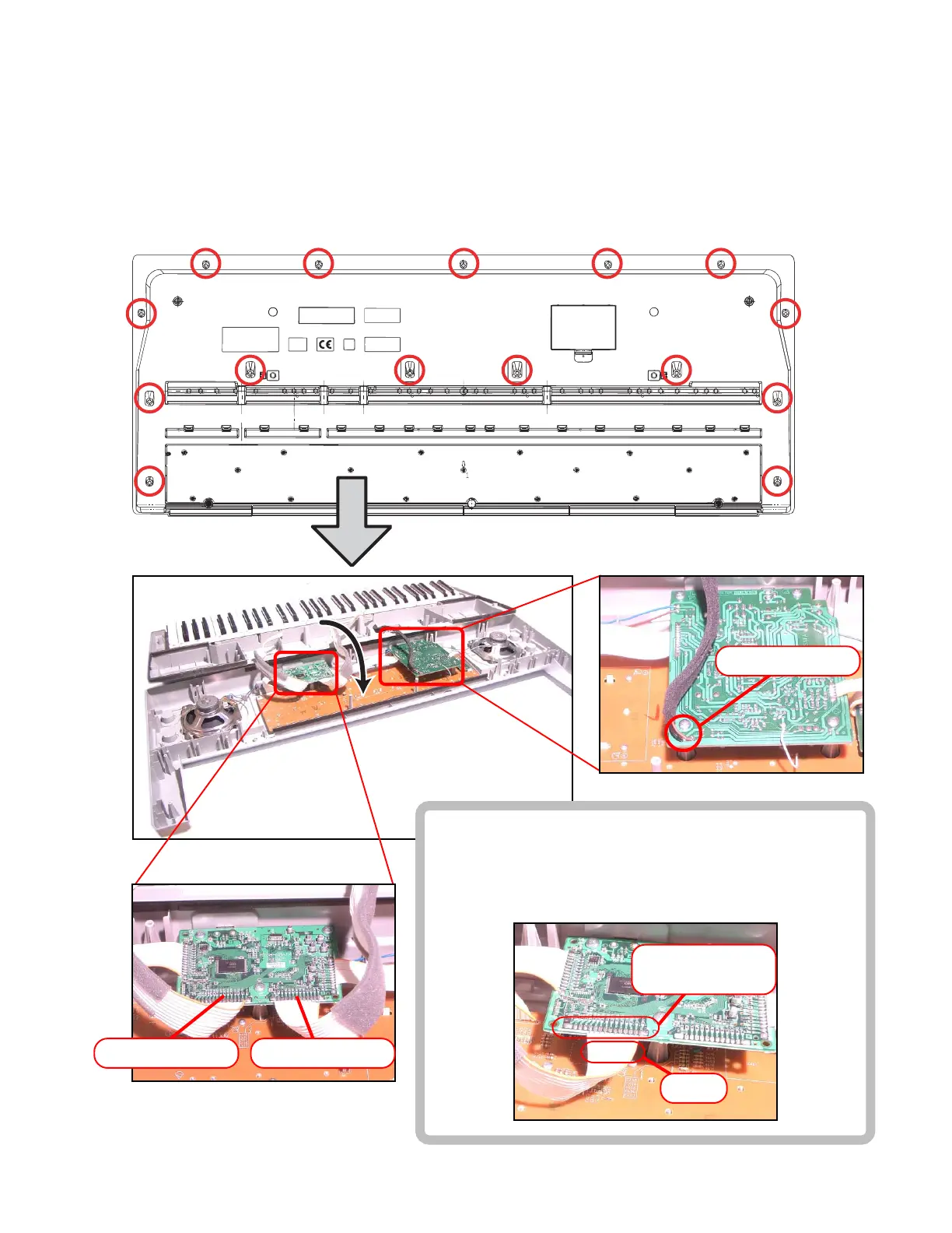
DISASSEMBLY
1. Remove the battery cover and then battery.
2. Remove 15 screws and then upper case.
3. Remove two lead wires by soldering.
4. Remove two connectors by soldering.
5. Make the keyboard unit and the main unit apart.
Lead wires
■ Precaution while assembling the main Connector 3.
Number of pins on the PCB and pins on the cable are
different.
Start connecting from the NO.1 pin whose color is orange.
Connector (CN2)Connector (CN3)
11 Pin
Connector (CN3)
15 pin