— 10 —
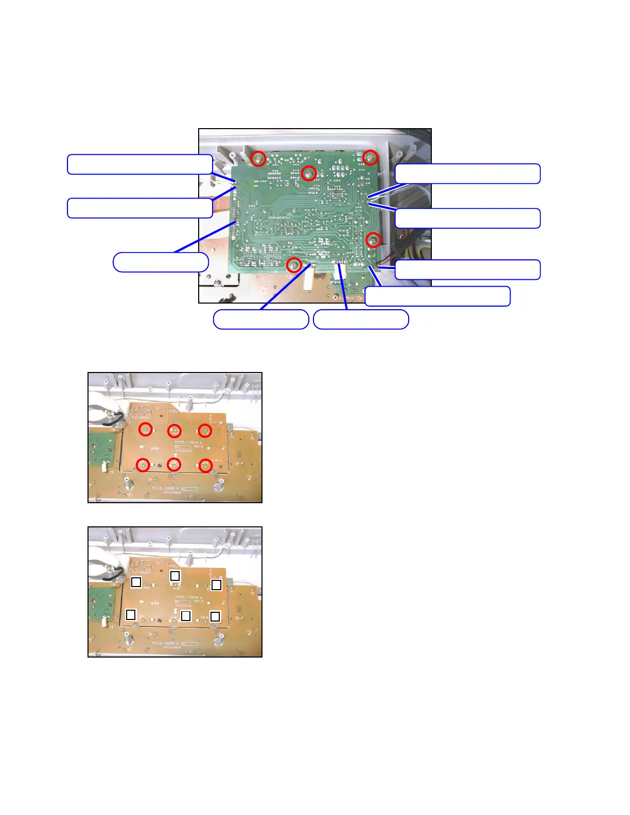
■ To remove the sub PCB (M705-MA2M).
6. Remove five screws on the PCB (M705-MA2M).
7. Remove three connectors on the PCB (M705-MA2M) by soldering.
8. Remove six lead wires on the PCB (M705-MA2M) by soldering.
9. Remove the PCB (M705-MA2M).
Connector (JB)
Connector (JB)
Connector (JB)
Speaker cord (orange)
Speaker cord (white)
Speaker cord (white)
Speaker cord (blue)
Battery cord (red)
Battery cord (black)
1
2
3
4
5
6
■ To remove LCD PCB (M705-LCD1M).
10. Remove six screws on the PCB ( M705-LCD1M).
Note: Tighten screws in order 1 to 6 as the figure shown below while reassembling.
 Loading...