— 12 —
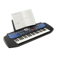
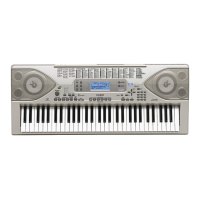
■ D301, D302
■ D303, D304
15.0 ± 0.5 mm
SOLDER SIDE
COMPONENT SIDE
14.5 ± 0.5 mm
SOLDER SIDE
COMPONENT SIDE
■ D305 ■ D306, D307
12.5 ± 0.5 mm
SOLDER SIDE
COMPONENT SIDE
6.8 ± 0.5 mm
SOLDER SIDE
COMPONENT SIDE
Anode
Cathode
D301 D302
D303
D304
D305
D306
D307
■ To replace LED.
Note: Fix the LED (D301, D302, D303, D304, D305, D306) to the PCB according to the height as shown in
the figure below while paying attention to the polarity.
Refer to the illustration on the PCB for the details of the polarity.
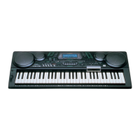
Note: Mount LED on the PCB. (solder side).
Correct polarity and height as follows.
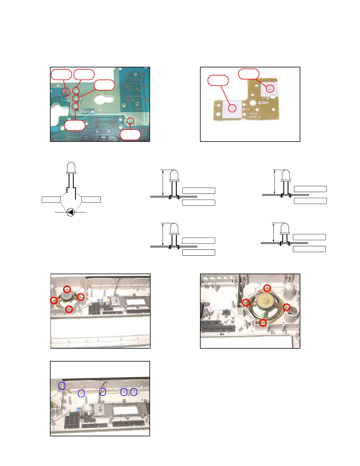
■ To remove the speaker.
18. Remove 8 screws and then two speakers.
Note: Fix speaker cords securely.
 Loading...