– 58 –
DT-X200/DT-X8
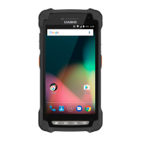
2. Peel off the tape, unlock the connector lock, and remove the FPC.
3. Remove the screws S1 (2 pcs.) and detach the NFC-UNIT.
(3) Removing the FRI-ASSY & EXT-UNIT
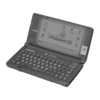
1. Remove the CAP-UNIT PCB.
2. Remove the screw S1 (1 pce.).
3. Remove the screws S7 (5 pcs.).
Note:
There are 4 screws in the NFC type.
Note:
The ground wire from the FRI-ASSY is also fastened at one screw.
FPC
Screws S1
NFC-UNIT
Screw S1
Screws S7
CAP-UNIT PCB
Screw S7
The ground wire is fastened
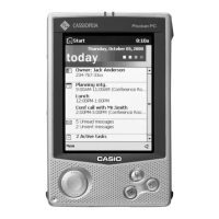
4. Remove the SBAT-HOLDER while paying attention to the antennas (2 places).
Note:
Gently lift the SBAT-HOLDER as the antennas are connected to it.
Antenna
Antenna
 Loading...