DISASSEMBLY AND REASSEMBLY: MODULE QW-51176.
HANDLING INSTRUCTIONS TO FIT THE SPACER6-1.
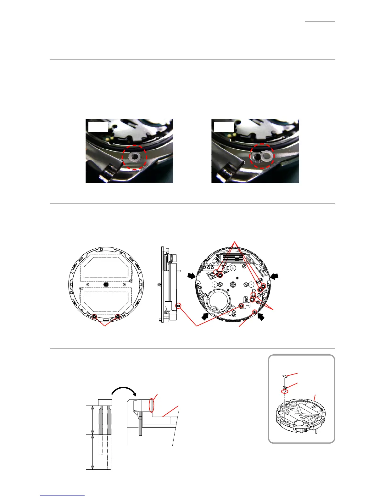
Inordertoincreasethesensitivityofsignalreception,thismodelisttedwithadoughnut-shaped
pacer at each of four screws assembling the back cover and the center piece. Be sure to align the
spacers correctly when/after repairing.
Furthermore, set the back cover in position gently so as not to misalign the spacer.
Note: Replace the spacer with a new one if it is found unclean or deformed.
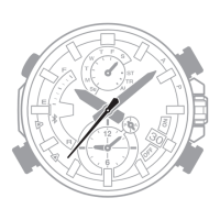
REMOVING THE MODULE6-2.
When removing the back cover, do not misplace the spring/coil.
Onremovingofthemodulefromthecase,pleaseinserttheprecisionscrewdriverbetweenthe
module and the case pointed by arrows.
REASSEMBLY OF LED6-3.
CuttheLEDasindicatedintheillustrationbelow.1)
AssembletheLEDwithitsleadfoldedinsidetheholder.2)
AttachtheTAPE/ADHESIVEontheuppersurfaceoftheLED.3)