— 3 —
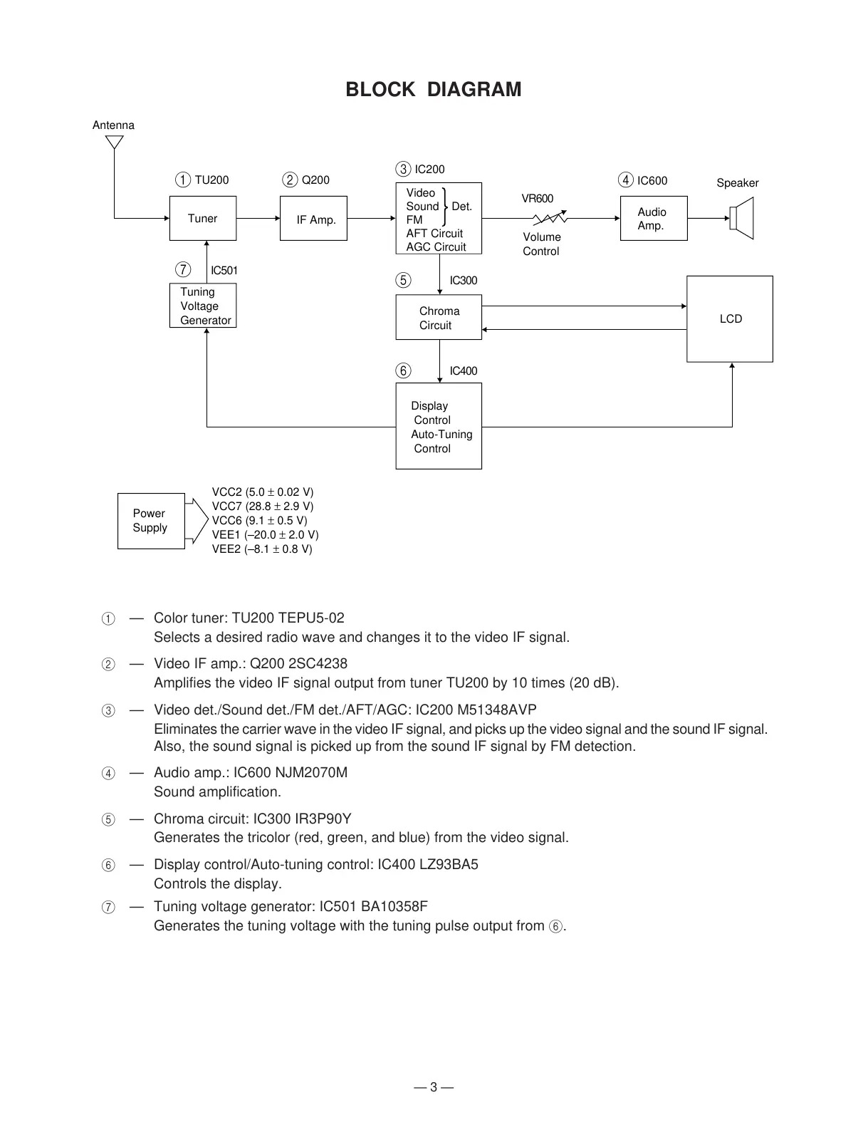
1 — Color tuner: TU200 TEPU5-02
Selects a desired radio wave and changes it to the video IF signal.
2 — Video IF amp.: Q200 2SC4238
Amplifies the video IF signal output from tuner TU200 by 10 times (20 dB).
3 — Video det./Sound det./FM det./AFT/AGC: IC200 M51348AVP
Eliminates the carrier wave in the video IF signal, and picks up the video signal and the sound IF signal.
Also, the sound signal is picked up from the sound IF signal by FM detection.
4 — Audio amp.: IC600 NJM2070M
Sound amplification.
5 — Chroma circuit: IC300 IR3P90Y
Generates the tricolor (red, green, and blue) from the video signal.
6 — Display control/Auto-tuning control: IC400 LZ93BA5
Controls the display.
7 — Tuning voltage generator: IC501 BA10358F
Generates the tuning voltage with the tuning pulse output from 6.
BLOCK DIAGRAM
Antenna
1
7
24
Speaker
VR600
IC501
IC300
IC400
Volume
Control
3
5
6
Power
Supply
VCC2 (5.0 ± 0.02 V)
VCC7 (28.8 ± 2.9 V)
VCC6 (9.1 ± 0.5 V)
VEE1 (–20.0 ± 2.0 V)
VEE2 (–8.1 ± 0.8 V)
Display
Control
Auto-Tuning
Control
Chroma
Circuit
Tuning
Voltage
Generator
Tuner
IF Amp.
LCD
Audio
Amp.
Video
Sound Det.
FM
AFT Circuit
AGC Circuit
TU200 Q200
IC200
IC600