— 21 —
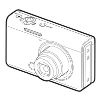
9. Disconnect the CONNECTOR, and then separate the LCD UNIT from the KEY UNIT.
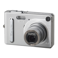
10. Remove the POWER UNIT.
NOTE: When assembling, align the POWER UNIT with
the position as shown below.
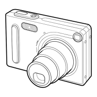
11.
Remove the two screws and disconnect the two CONNECTORs, and then remove the MAIN PCB and the speaker.
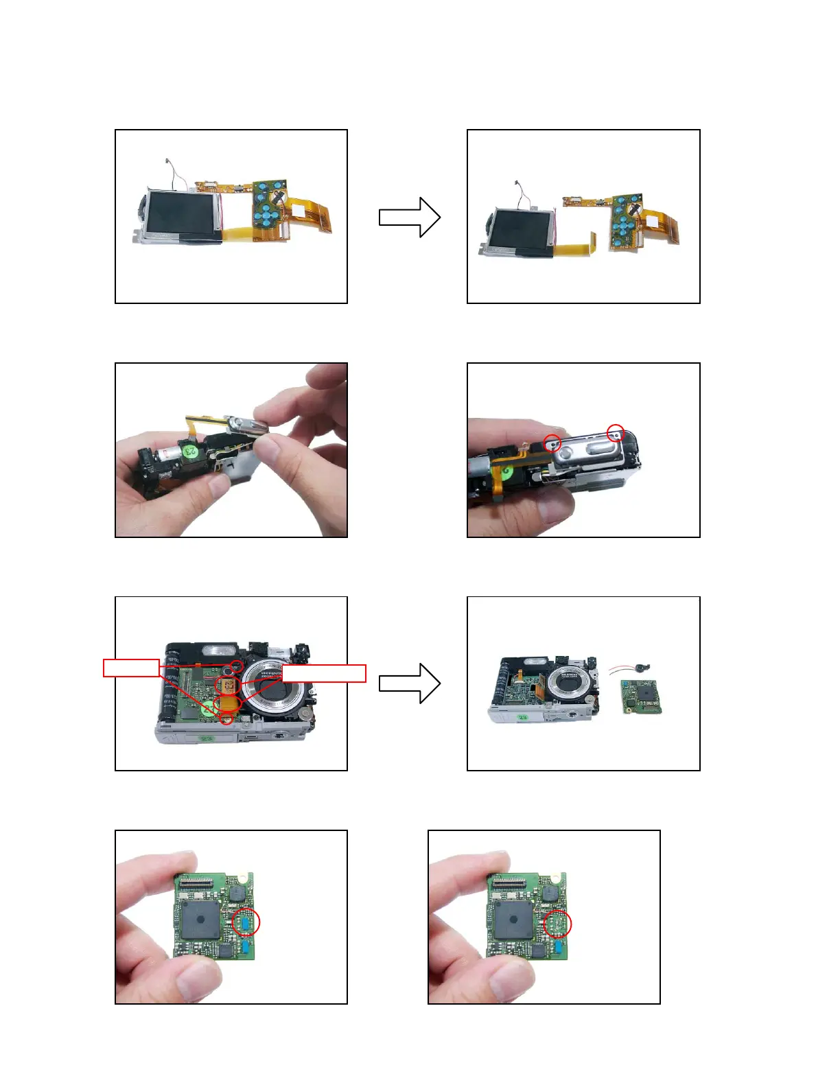
NOTE: Discriminating between the two MAIN PCBs
A TYPE: IC215 mounted B TYPE: IC215 not mounted
screws
connectors