— 37 —
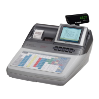
Signal Pin
SD 1
RD 2
FG FG plate
(In-line connector)
Signal Pin
SD 1
RD 2
FG FG plate
(In-line connector)
Signal Pin
SD 1
RD 2
FG FG plate
(In-line connector)
Terminater
100 ohms
Terminater
100 ohms
3 ARCNET Cable connection diagram
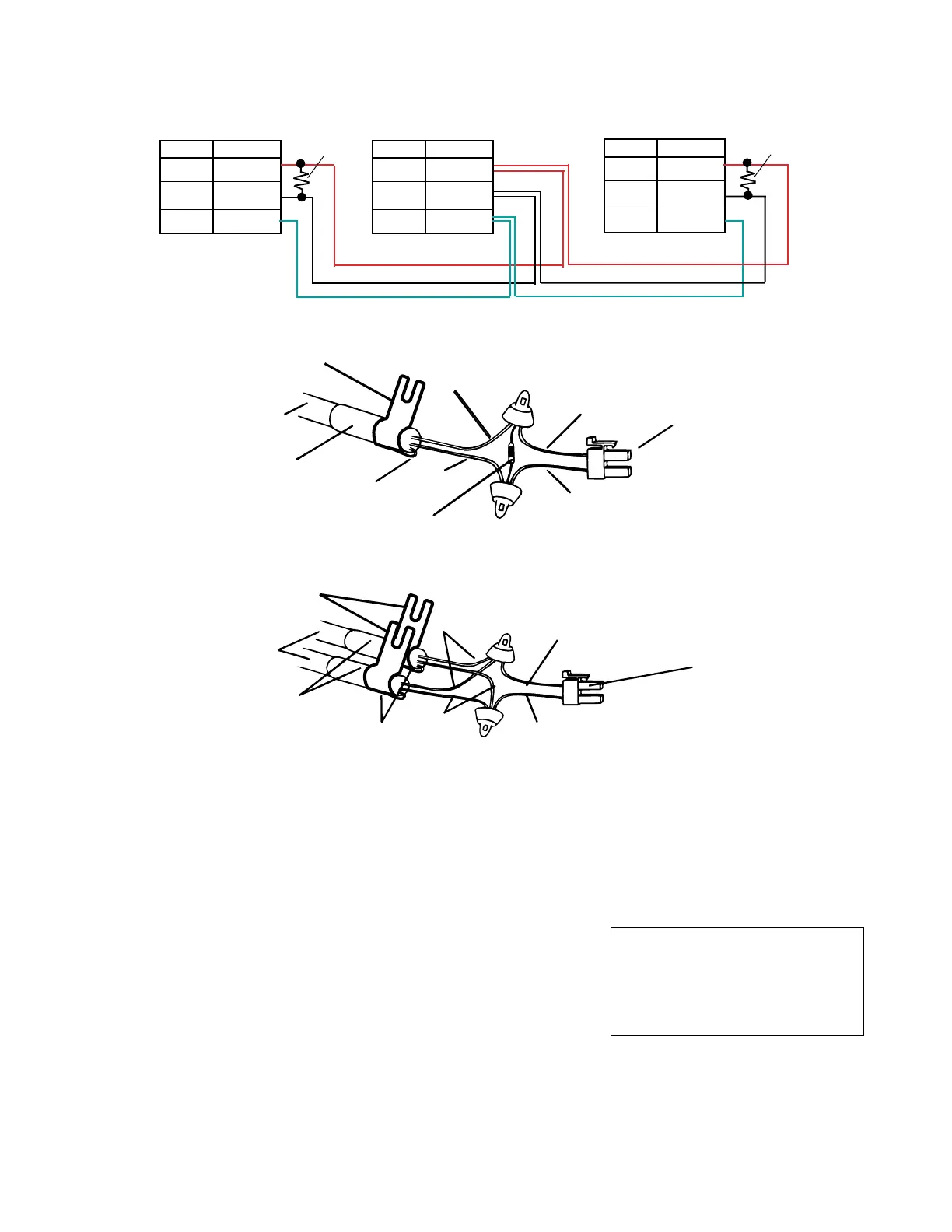
[Connection between ECR and ECR]
Shield wire
Terminator (100 ohms)
In-line cable
In-line connector
Red
Wrap bent shield wire
with Copper tape
Red
Black
Black
Earth plate
In-line connector
Red
Black
Black
Red
In-line cable
Wrap bent shield wire
with Copper tape
Shield wire
Earth plate
[Connection end of ECR]
7-2. CATEGORY5 (INLINE2)
1 Restrictions
• Maximum number of units that can be connected is 32.
• HUB and rooter cannot be connected.
• With ARCNET simultaneous use impossible.
• Minimum cable length between units is 5 meters.
2 APPLICATION
• Auto PGM
• Sales Data Collection
• Shared Check Tracking
• Shared Printer
• IPL
Maximun total length of the cable
4 units : 450m
8 units : 420m
32 units : 230m
NOTE:
1) The earth plate should be fixed to the ground chassis.
2) When using the ARCNET, slide the switch at the bottom of ECR to RS485.
 Loading...