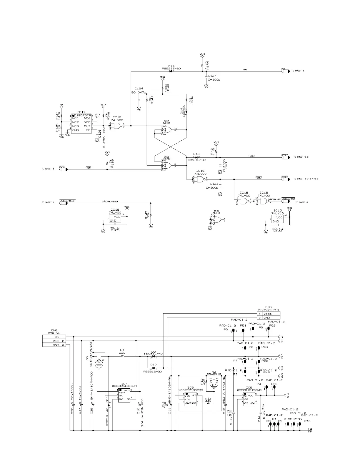
EasyManuals Logo

Casio TE-8000F Service Manual

Casio TE-8000F
150 pages
To Next Page IconTo Next Page
To Previous Page IconTo Previous Page
Page #21 background imageLoading...
Page #21 background image
19
5-3. RESET CIRCUIT
The reset circuit is as follows.
Reset IC
5-4. POWER SUPPLY CIRCUIT
The power supply circuit is as follows.
VP (DC 25.2V): For the printer control circuit.
VCC (DC 5V): For the logic circuit power.
V3.3 (DC 3.3V): For the logic circuit power.
Vbat (DC 3.3V): For the RAM power.
V1.9V (DC 1.9V): For the CPU internal power.
Vrtc (DC 1.9V): For the CPU RTC power.

Other manuals for Casio TE-8000F

Questions and Answers:

Question and Answer IconNeed help?

Do you have a question about the Casio TE-8000F and is the answer not in the manual?

Casio TE-8000F Specifications

General IconGeneral
BrandCasio
ModelTE-8000F
CategoryCash Register
LanguageEnglish

Related product manuals