V-R7000/V-R7100
– 35 –
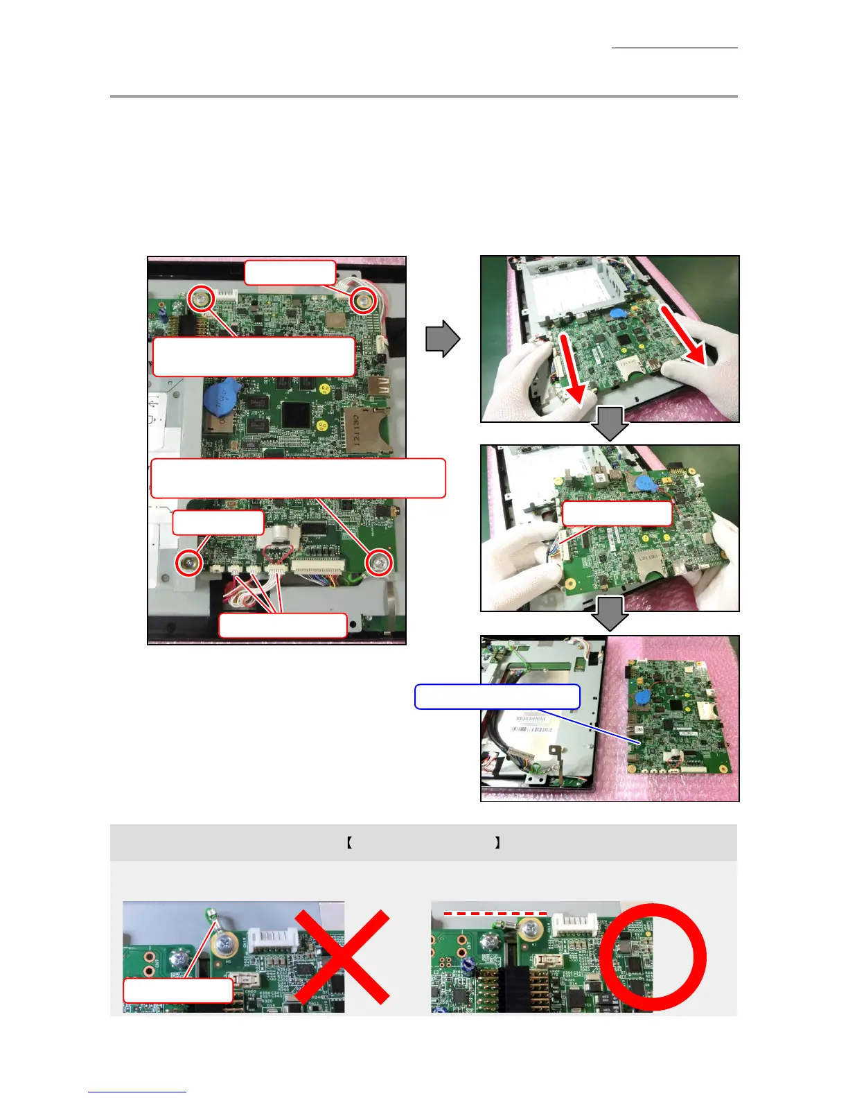
C. PCB UNIT/MAIN
NOTE: Two wireless LAN antenna cables are attached with a new PCB UNIT/MAIN for V-R7100.
Replace the current antenna cables with new ones as required.
C-1. Disconnect three connectors.
C-2. Undo four screws.
C-3. Remove the PCB UNIT/MAIN by sliding it sideways.
C-4. Disconnect one connector.
Connector
Connectors
Screw (S3)
Fix the ground wire together.
Screw (S3)
Screw (S3)
PCB UNIT/MAIN
Screw (S3)
Fix the ground wire and the earth plate together.
Note on reassembling
• Pay attention to the orientation of the ground wire. If the orientation is improper, the BACK CHASSIS
ASSY cannot be assembled properly.
Ground wire

 Loading...