V-R7000/V-R7100
– 36 –
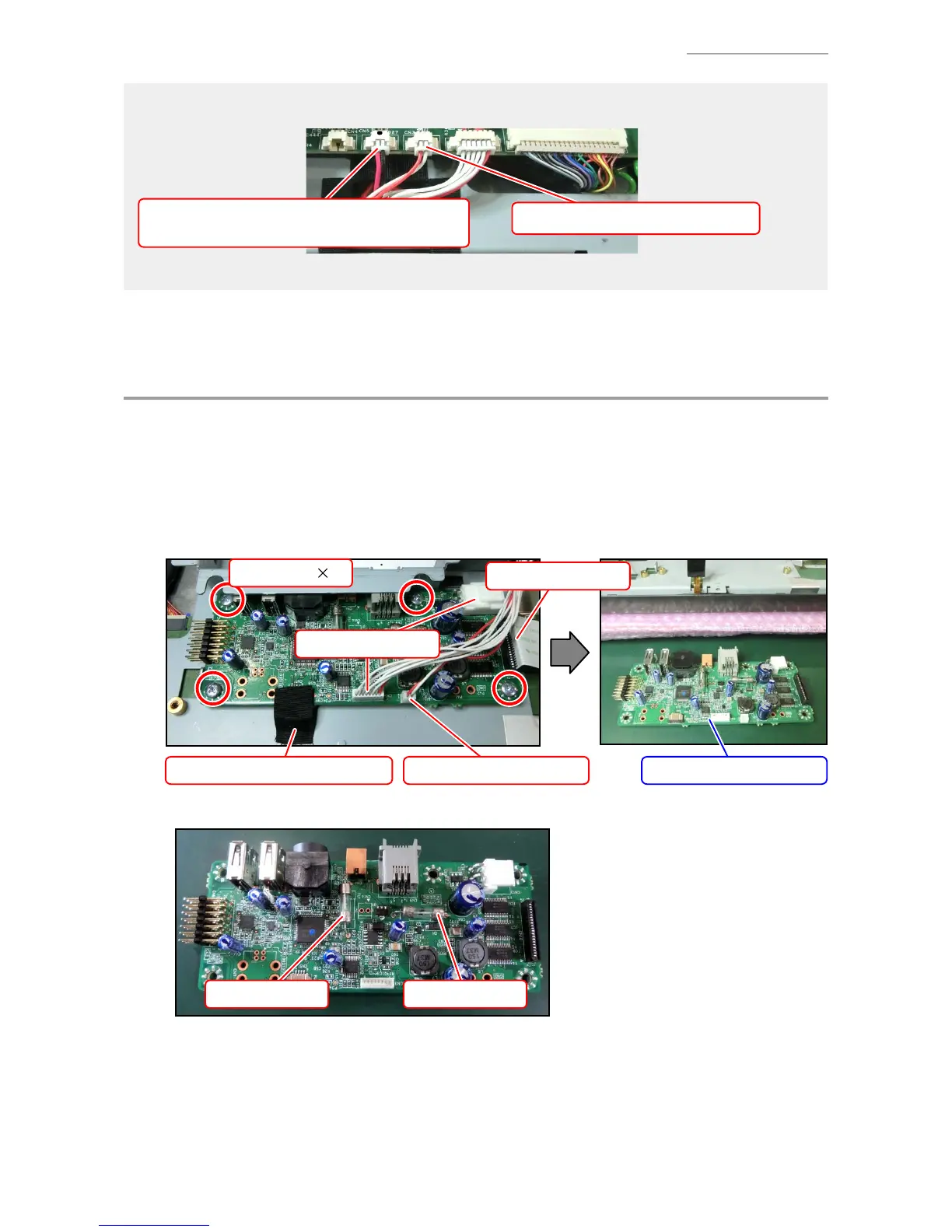
• Do not mix up the connectors for the speaker and the microphone.
Speaker (Lead wires: red, black)
A black dot is marked on the PCB side connector.
Microphone (Lead wires: red, white)
D. PCB UNIT/IOC
NOTE: The PCB UNIT/IOC cannot be removed if the PCB UNIT/MAIN is not removed yet.
D-1. Disconnect two connectors. (Three connectors for the Dallas key model)
D-2. Disconnect one connector.
D-3. Peel off one tape, release the connector lock, and disconnect the FPC.
D-4. Undo four screws.
Screw (S3) 4
Connectors
Connector (Dallas key)
FFC
Tape
Unlock
FPC PCB UNIT/IOC
TIPS: Fuse information
FU1 FU2

 Loading...