V-R7000/V-R7100
– 37 –
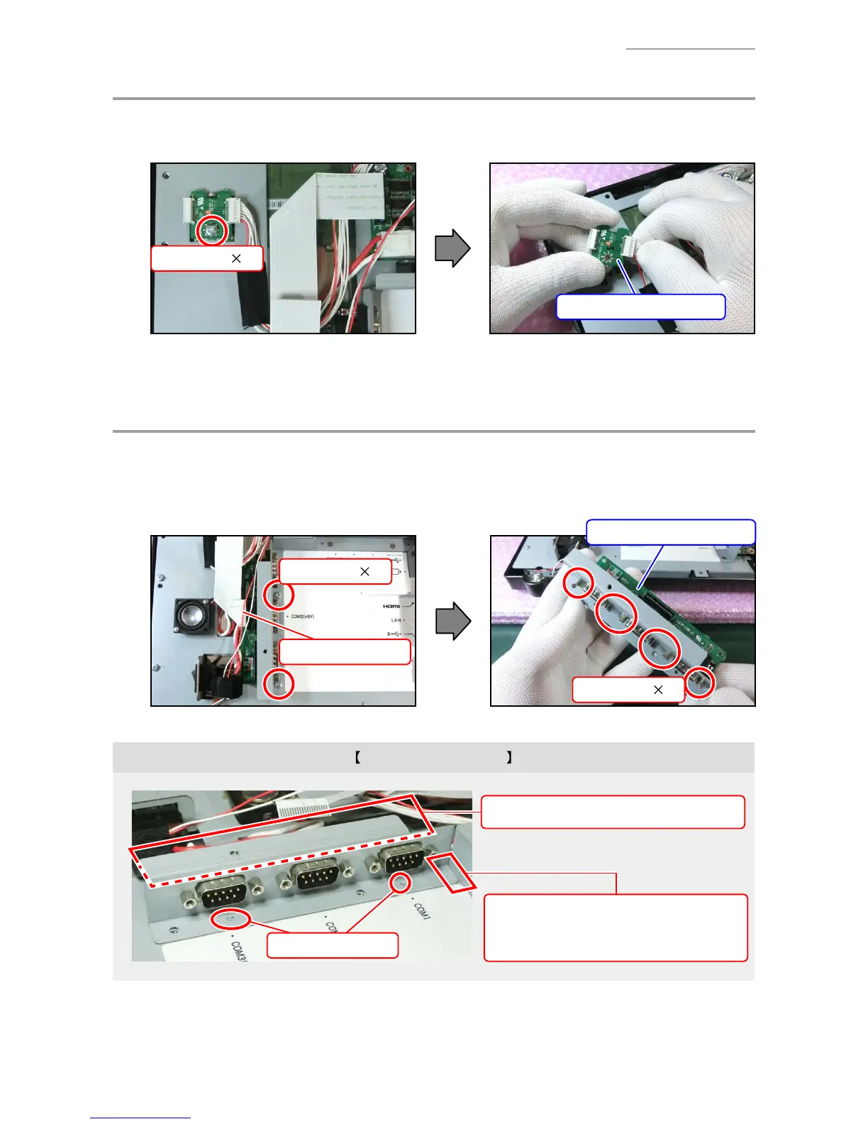
E. PCB UNIT/MCR
E-1. Undo one screw.
E-2. Disconnect one connector.
Screw (S3) 1
PCB UNIT/MCR
F. PCB UNIT/COM
F-1. Disconnect one FFC.
F-2. Undo two screws and remove the PLATE/SUB.
F-3. Undo six lock screws and remove the PCB UNIT/COM.
Screw (S3) 2
FFC
PCB UNIT/COM
Lock screw 6
Note on reassembling
Positioning places
Be sure that no cables are pinched.
The PLATE/SUB might be hard to assemble
in the engaging portions of plates.

 Loading...