V-R7000/V-R7100
– 38 –
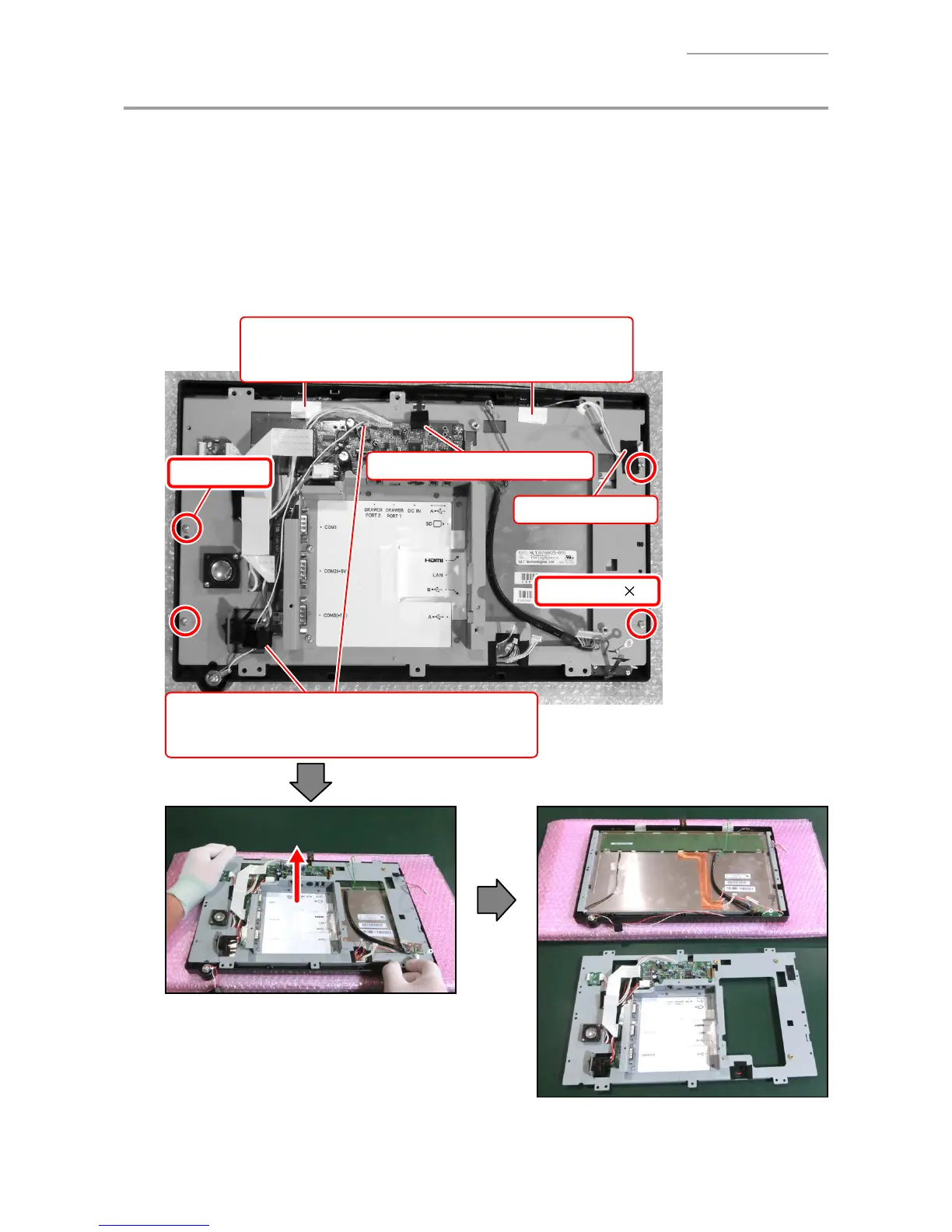
G. PCB CHASSIS ASSY
NOTE: The PCB CHASSIS ASSY cannot be removed if the PCB UNIT/MAIN is not removed yet.
G-1. Peel off one tape, release the connector lock, and disconnect the FPC.
G-2. Peel off one tape.
G-3. Remove two antennas (silver parts). (V-R7100 only)
G-4. Undo four screws.
NOTE: Two kinds of screws are used. (S2
×
1, S3
×
3)
G-5. Disconect one connector and remove a ferrite core. (Dallas key model only)
Tape
Unlock
FPC
Screw (S2)
Screw (S3) 3
Tape
Wireless LAN antenna
×
2
NOTE: Carefully peel the antenna so as not to tear it.
Dallas key model
Disconect one connector and remove a ferrite core.

 Loading...