Do you have a question about the Casio DT-940 and is the answer not in the manual?
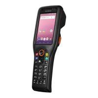
Details the different models in the DT-930/DT-940 series and their features.
Describes optional accessories such as cradles and AC adapters for the handheld terminals.
Provides detailed technical specifications for the device's hardware and communication capabilities.
Outlines essential precautions for handling, operating, and storing the device safely.
Instructions for handling, loading, and removing main and backup batteries for the terminal.
Explains how to turn the unit on/off, special key operations, and reset procedures.
Provides a flowchart illustrating the sequence of disassembly for the handheld terminal.
Illustrates and identifies the various types of screws used for assembly and disassembly.
Step-by-step instructions for opening and closing the main case of the device.
Procedures for disassembling and assembling the laser module, mirror, and laser holder.
Instructions for removing the IO-ASSY and Buzzer components from the unit.
Steps for disassembling the Sub-ASSY and the vibration motor unit.
Procedures for removing the I-CASE and separating the main board.
Instructions for disassembling and assembling the LCD module and trigger keys.
Details on key assembly, tape application, and cable handling during disassembly.
Guides the user through the process of updating the firmware for the DT-940.
Instructions for changing the system language from Japanese to English.
Explains how to start, terminate, and perform common operations within the diagnostic program.
A comprehensive list of all available diagnostic programs with their functions.
Detailed procedures for running specific diagnostic tests such as RAM, FROM, and LCD checks.
Provides a list of error codes encountered during diagnostics and their interpretations.
Lists the essential files required to perform Bluetooth connectivity diagnostics.
Outlines the methodology for diagnosing Bluetooth functionality using two machines.
Step-by-step instructions for executing the Bluetooth diagnostic procedure.
Lists the files required to perform the laser scanner check on the DT-940.
Detailed steps for conducting the laser scanner diagnostic test.
Explains the necessity and context of bar code calibration for the device.
Provides instructions on how to perform the bar code calibration setting procedure.
Details revisions and changes in internal components across different models and types.
Identifies and lists connectors on the main printed circuit board (PCB).
Illustrates the internal system architecture and component interconnections.
Shows an exploded view of the entire handheld terminal assembly.
Displays an exploded view of the upper case and its components.
Displays an exploded view of the lower case and its components.
Displays an exploded view of the inner case and its components.
Illustrates the locations of labels and lists bundled accessories.
Lists all parts included in the final assembly of the handheld terminal.
Lists all parts comprising the upper case assembly.
Lists all parts comprising the lower case assembly.
Lists all parts comprising the inner case assembly.
Lists parts related to labels, bundled items, and tools.
Provides a detailed parts list for the HA-E60IO accessory.
| Brand | Casio |
|---|---|
| Model | DT-940 |
| Category | Touch terminals |
| Language | English |