― 21 ―
3.3.11 LCD DISASSEMBLY/ASSEMBLY
Procedures
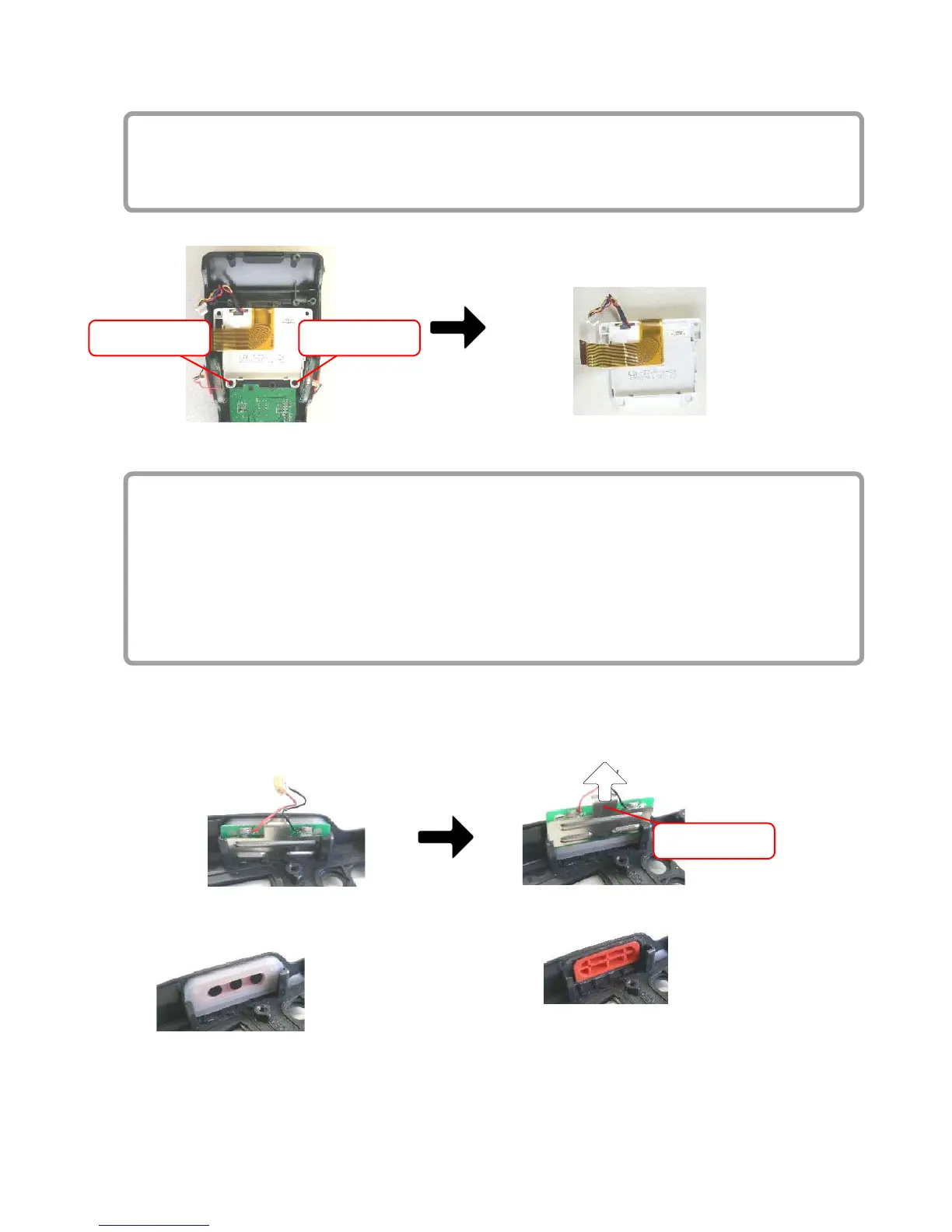
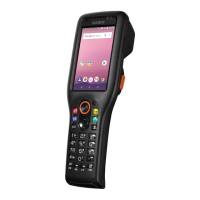
(1) Remove two B screws (+, silver).
(2)
Detach LCD.
* For the assembly, reverse the above order.
(1) B Screw (1) B Screw
(2) Hold up and detach LCD after removing two B screws (1).
3.3.12 TRIGGER-KEY DISASSEMBLY/ASSEMBLY
Procedures
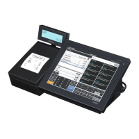
(1) Remove TRIGGER-HOLDER on both sides of the case by pulling it upward, using the hook.
(2)
Remove TRIGGER-ASSY.
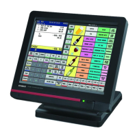
(3) Remove TRIGGER-RUBBER.
* It is xed to L-CASE with a W tape.
(4)
Remove TRIGGER-KEY.
* Left and right TRIGGER-KEYS are not identical.
* For the assembly, reverse the above order.
< Caution > Do not pinch the cables.
(1) Pull TRIGGER-HOLDER upward, using a hook. If solders on TRIGGER-ASSY block the motion, pull
out TRIGGER-HOLDER together with TRIGGER-ASSY. Be careful about the cables which are very
thin.
hook
(3) Remove TRIGGER-RUBBER.
* It is xed to L-CASE with a W tape.
(4) Take out TRIGGER-KEY.