― 11 ―
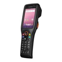
3. DISASSEMBLY/ASSEMBLY
The disassembly/assembly of the DT-930/940 must be carried out according to the basic owchart below.
Starting from the rst step in the owchart and removing each part allows you to reach the target part.
For the disassembly/assembly of each part and ASSY, follow the procedures stated in each section.
3.1 BASIC FLOWCHART
The following is the basic owchart for the disassembly of the DT-930
/940
. Each removable main part
can be removed by detaching Parts (1) and (2).
Failure to follow the procedures may damage the connectors or other parts.
Start
BATTERY-COVER
(1) Open L-CASE.
SUB-BATTERY-COVER
LASER-HOLDER
LASER-MODULE
(2) Remove I-CASE.
MAIN-BOARD
LCD
TRIGGER-KEY/L, R
KEY
U-CASE
MAIN BOARD can be removed by detaching the bold-frame parts in the flowchart. (~)
There are some parts whose connectors must be removed.
Removable Main Parts
1
2
3
SUB-ASSY IO-ASSY BUZZER
VIBRATION-MOTOR
4
5
6
MIRROR
* Down-facing reader
port model only
LASER-BASE
* DT-940 only
LF-HOLDER
LASER-FILTER
* DT-940 only