V-R7000/V-R7100
– 42 –
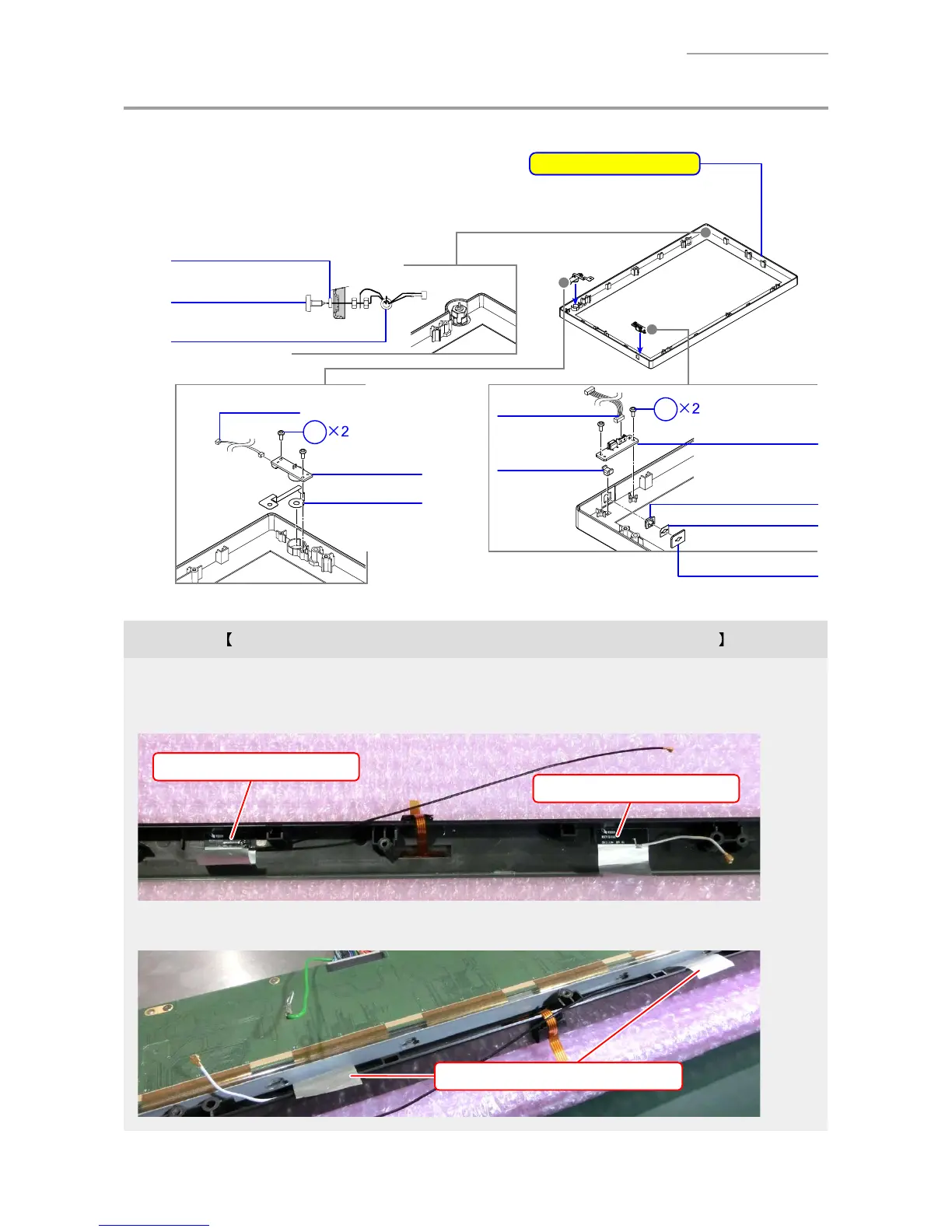
I. FRONT-CASE-ASSY
I-1. The parts confi guration of the FRONT-CASE-ASSY is as follows.
Dallas key model only
S4
S4
FG/PLATE/MIC
PCB UNIT/MIC
BUTTON/POWER
TAPE/BUTTON
PCB UNIT/LED
CUSHION/BUTTON
CABLE/MIC
LENS/LED
CABLE/LED
DALLAS ASSY
FERRITE CORE
SPACER/DALLAS
FRONT-CASE-ASSY
* Including Touch Panel
Note on replacing the CASE ASSY/FRONT of the wireless LAN model
• Two wireless LAN antennas are attached with the PCB UNIT/MAIN and they are not available.
Carefully peel the two antennas from the FRONT-CASE-ASSY to be replaced, and then stick them to a
new FRONT-CASE-ASSY.
Antenna (Black lead wire)
Antenna (Gray lead wire)
NOTE: Stick the antenna’s silver part (with adhesive tape) after assembling the PCB CHASSIS ASSY.
Adhesive tape part (silver part)

 Loading...