EasyManuals Logo

Casio WK-1800 Service Manual

Casio WK-1800
44 pages
To Next Page IconTo Next Page
To Previous Page IconTo Previous Page
Page #10 background imageLoading...
Page #10 background image
— 9 —
POWER SUPPLY CIRCUIT
The power supply circuit provides various voltages as shown below.
The voltage VDD (+5 V) is provided as long as batteries or AC adaptor is set.
Other voltages are controlled by APO (Auto Power Off) signal from CPU.
The regulator IC BA9700A generates square waveform from pin 5 as PWM (Pulse Wide Modulation).
The LC filter makes stable output voltage (+5 V) for each circuit as shown above.
LC Filter
(To digital)
(To analog)
(To FDD)
(To LCD)
CPU
HD6433048SA89F
LSI9
PA 7
NMI
PW/SW
APO
NMI
PW/ON
APO

Other manuals for Casio WK-1800

Questions and Answers:

Question and Answer IconNeed help?

Do you have a question about the Casio WK-1800 and is the answer not in the manual?
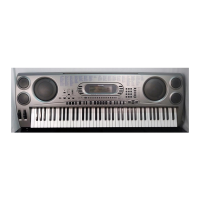
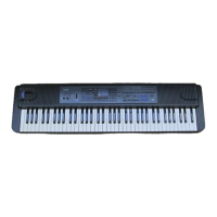
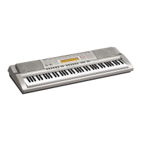
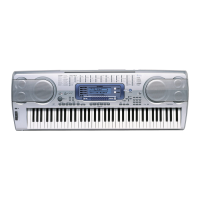
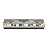
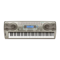
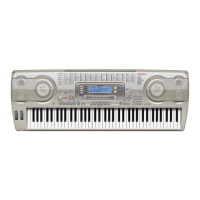
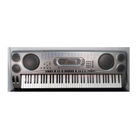
Casio WK-1800 Specifications

General IconGeneral
Number of Keys76
MIDIYes
DisplayLCD
EffectsReverb, Chorus
Weight8.5 kg
Polyphony32
SpeakersYes
Power SupplyAC adapter or batteries
Floppy Disk DriveYes
ConnectionsHeadphones, MIDI In/Out, Sustain pedal
Sequencer6 tracks

Related product manuals