- 5 -
Means for disconnection must be incorporated in the fixed wiring in accordance with the wiring rules.
− The electric cable must be positioned so that it cannot reach a temperature of over 75 C at any point.
− Do not use reducers, adapters or shunts for the connection as they could cause false contacts and subsequent dangerous
overheating.
When the connection is made directly with the electricity supply:
−
Place a single-pole switch between the appliance and the electricity supply. The switch must be of a suitable charge for the
appliance with a minimum opening between the contacts of 3mm.
− Remember that the earth wire must not be interrupted by the switch.
− Alternatively the electrical connection can also be protected by a differential switch of high sensitivity.
− You are strongly advised to fix the special yellow-green earth wire to an efficient earthing system.
MAINTENANCE OF THE MACHINE
CHANGING THE PARTS
Before carrying out any maintenance work, disconnect the appliance from the gas and electric supply.
In the event of wear or damage to the mains cable, replace the cable with one of the same rating.
TABLE N
o
2: Types and sections of the electric mains cable for hobs
Type of hob Type/section of mains cable
Gas burners+ electric plate./4 electric plate H05RR-F 3x1 mm
2
WARNING: If you replace the electric mains cable, the installer must have the earth conductor about 2 cm longer
t
han the phase conductors and must also take heed of the warnings regarding electric connection.
O
iling the taps: (This must be carried out by qualified staff from a technical assistance centre )
If a tap becomes difficult to move you must oil the tap, without delay, following the instructions given below.
1) Dismantle the main part of the tap by unscrewing the two screws that can be found on the bar of the tap itself. (Fig. 6)
2) Take out and clean the holding cone and its setting with a cloth soaked in diluents.
3) Oil the cone lightly with the special oil.
o
4) Insert the cone, move it a few times, take it out again, remove the excess oil and make sure that the areas where the gas flows are
not obstructed.
5) Reassemble all the pieces in the reverse order to that followed for the dismantling and check that the cap is working properly.
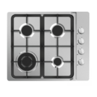
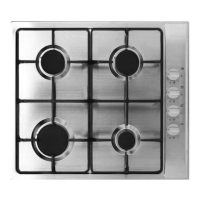
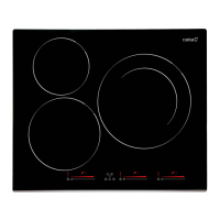
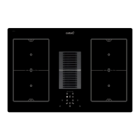
DESCRIPTIVE CAPTION FOR HOB
(
Fig. 7)
(
Figs. 5-1 – 5-4)
1. Auxiliary burner
2. Semi-rapid burner
3. Rapid burner