ALL EQUIPMENT MUST HAVE A MAINLINE (ML) CONTACTOR INSTALLED AND ALL
TRACKED EQUIPMENT (I.E., CRANES) MUST HAVE A BRAKE INSTALLED.
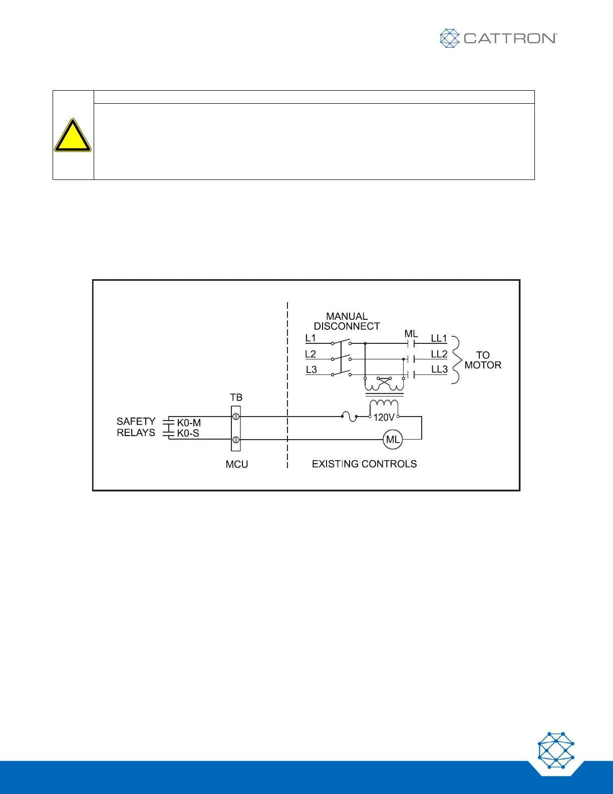
THE REMOTE CONTROL SAFETY RELAYS MUST BE CONNECTED TO THE MAINLINE SO
THAT STOP COMMANDS WILL DE-ENERGIZE THE MAINLINE CONTACTOR AND SET THE
EQUIPMENT BRAKE.
FAILURE TO COMPLY WITH THE ABOVE WARNINGS MAY RESULT IN SERIOUS INJURY OR
DEATH TO PERSONNEL AND DAMAGE TO EQUIPMENT.
The safety relays are energized for the first time when the MCU has power applied, the OCU is switched on, and
a matching address code is sent from the OCU via a radio frequency (RF) signal to the MCU.
The safety relays must be wired to the mainline (ML) contactor.
Switching the OCU to ‘ON’ energizes the mainline contactor.
Once the mainline is energized, a continuously repeated valid signal must be received for function outputs to
engage. If this signal is interrupted for any reason, all function outputs will switch off.
Figure 19: Basic Safety Relay Contact Wiring
6.6 Transfer Switch
A Transfer Switch (Type HM254-73, Part Number 452031) provides an easy way to switch the controlled
equipment from manual to remote control. If the equipment is to be operated in the radio only mode and there
are no manual controls, the transfer switch can be omitted. Otherwise, installation of a transfer switch is
desirable to allow selection between radio or manual operation.
Installing the transfer switch may require changes to the controlled equipment wiring. Prior to changing any
existing wiring, create a wiring diagram of the planned changes. Use existing empty terminals on terminal boards
as tie points.
 Loading...