EasyManuals Logo

Cattron CT24 Series User Manual

Default Icon
56 pages
To Next Page IconTo Next Page
To Previous Page IconTo Previous Page
Page #20 background imageLoading...
Page #20 background image
CT24 MCU
User Manual
20
9M02-7608-A001-EN
Version 2.0
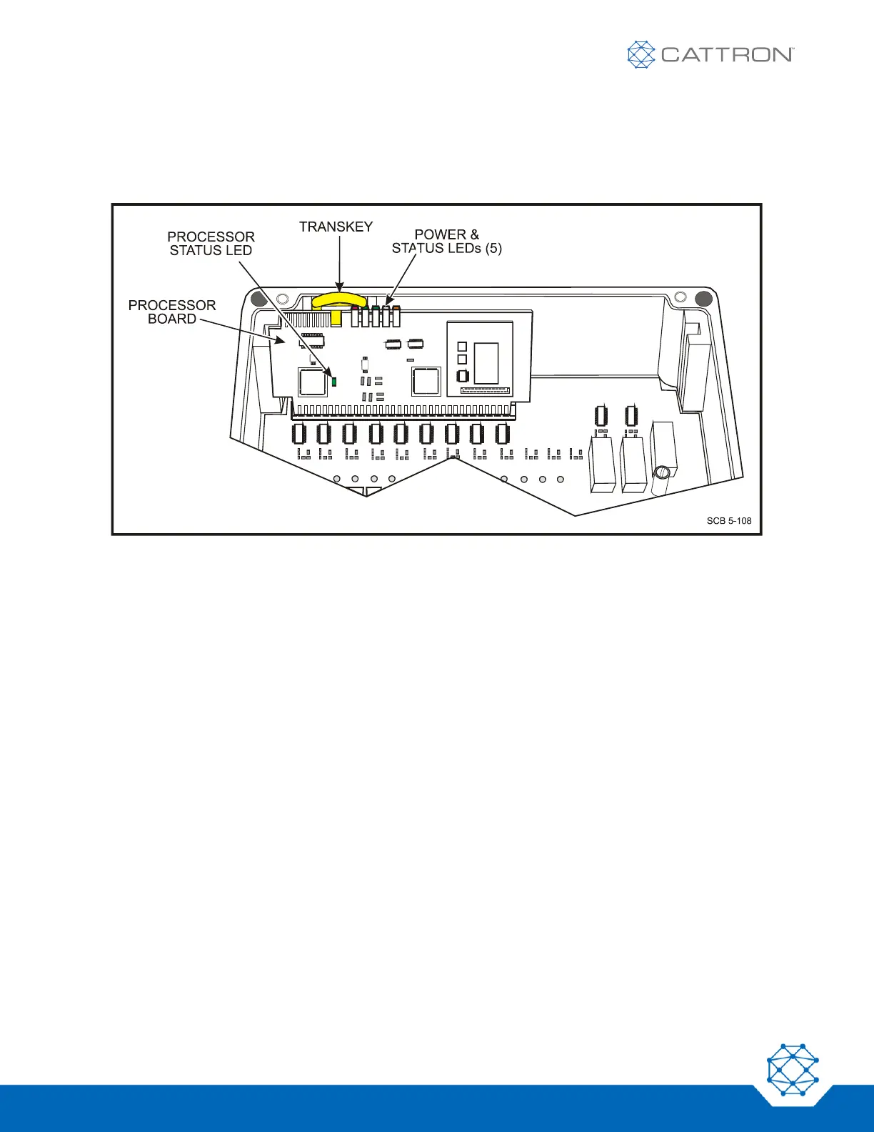
Referring to Figure 7, an additional processor status LED indicator is mounted on the MCU processor board and
may be viewed by removing the MCU front cover. This LED blinks orange if the receiver does not detect a
transmitter and green if valid messages are received. In addition, if the second processor detects a fault, this LED
blinks red.
Figure 7: MCU Status and Fault LEDs
4.1.1 Optional 9-36 VDC Input MCU
An optional 9-36 VDC input MCU, Part Number 1MCU-7608-A103, is available. This MCU is identical to the
standard MCU except that the power supply on the relay board is changed.

Table of Contents

Questions and Answers:

Question and Answer IconNeed help?

Do you have a question about the Cattron CT24 Series and is the answer not in the manual?

Cattron CT24 Series Specifications

General IconGeneral
BrandCattron
ModelCT24 Series
CategoryControl Unit
LanguageEnglish

Related product manuals