9M02-7608-A001-EN
Version 2.0
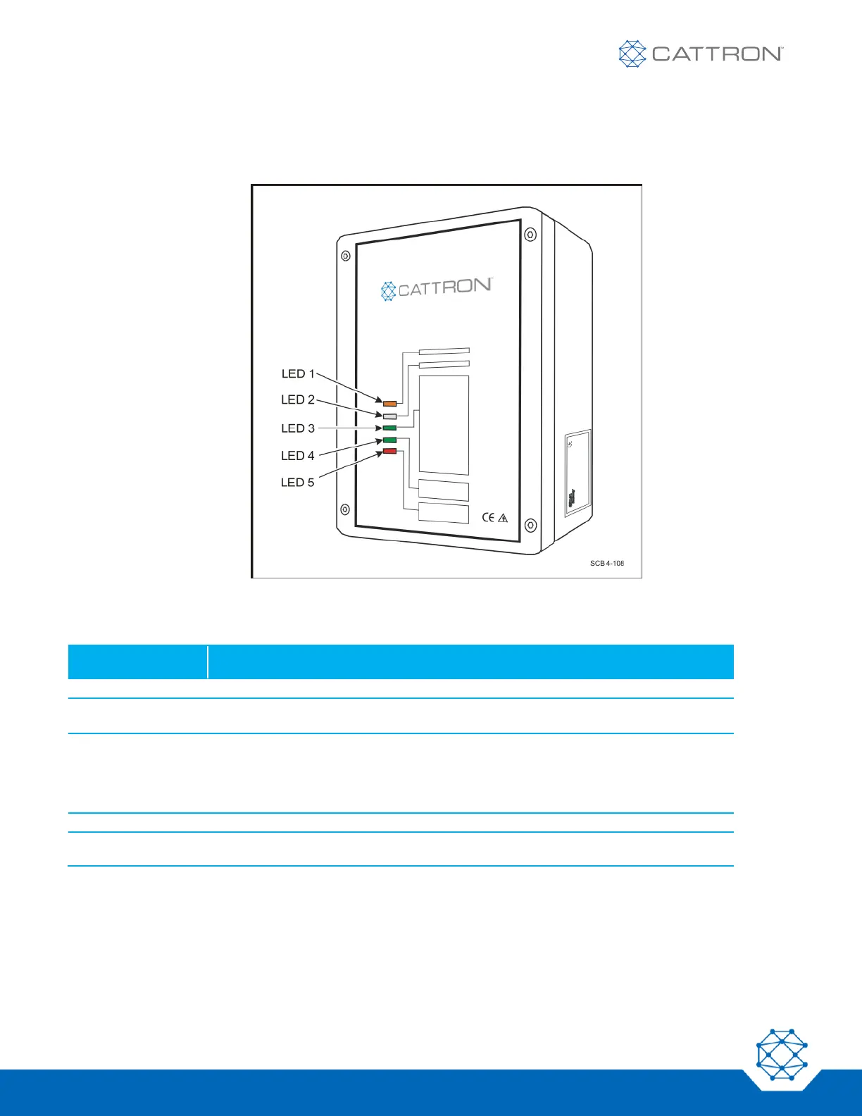
As illustrated in the following figure, all CT24 MCUs have five externally visible LED indicators on the front cover
that display the current system status to the operator. The status/fault messages associated with each LED are
described in Table 1.
Figure 6: MCU System Status LEDs (all CT24 versions)
Table 1: MCU External Status/Fault LED Messages
MCU EXTERNAL
LED INDICATORS
Illuminates orange when the MCU receiver has voltage
Flashes red/orange in Scan Mode
Not used when system is configured for fixed frequency
Illuminates green when valid data from the OCU is received and both safety
relays are energized
Illuminates orange if valid data from the OCU is received and the safety relays are
de-energized
Illuminates red if data from another OCU (with invalid address) is received
Illuminates green when commands are received from the OCU (normal condition)
Blinks red when the MCU detects a fault (refer to the Appendix on Error Codes for
the blink sequence and the corresponding fault messages)
 Loading...