Installation rules:
1. The antenna extension (co-axial) cable is to be no longer than required, and at most 50 feet long (without
further reference from your supplier).
2. Co-axial cable should be of type RG58AU or similar.
3. If the co-axial cable is connected to an antenna that is mounted on the outside of a secondary enclosure,
it may be taken directly from the MCU enclosure to the secondary chassis mount connector. The co-axial
cable should be mounted securely and kept away from all power carrying conductors.
4. If the co-axial cable is going to an antenna remote from the MCU location, it must be kept separate from
any power carrying conductors and mounted within a metallic conduit system for protection.
5. If the MCU is mounted within a secondary enclosure, the metallic conduit should be correctly mounted
with earth bonding to the secondary enclosure.
6. If the MCU enclosure is mounted directly to the crane/machine, a terminating junction box must be
installed adjacent to the antenna connector with a suitable gland for the co-axial cable to exit and connect
to the antenna connector on the MCU.
7. Conduit shall not be connected directly to the MCU enclosure as there is no provision for grounding it
within the MCU.
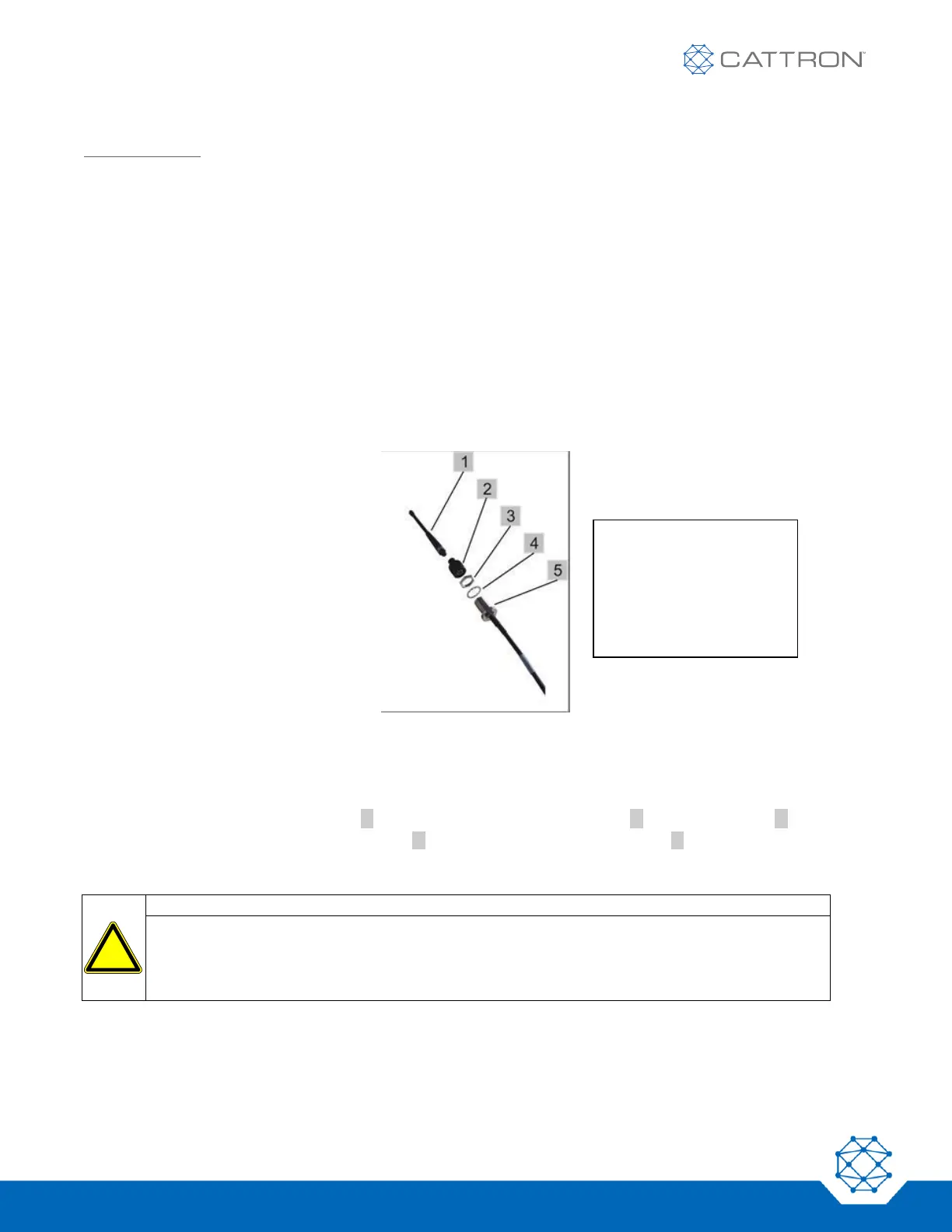
Figure 21: Remote Antenna Parts
If you have ordered an optional “remote antenna”, there will be a connector for the antenna cable at the top of
receiver enclosure.
1. Install the antenna at a location from where a good visual connection to the handheld transmitter exists.
2. Fix the mountable N connector [5] ( 15 mm) using the spring washer [4] and the fixing nut [3].
3. Push and screw the N to FME adaptor [2] to the jack and screw the antenna [1] to the FME-connector.
4. Route the antenna cable to the receiver and attach it to the connector at the transmitter enclosure.
Hazard of short circuits inside the housing:
The antenna connector cable inside the MCU enclosure is retained within a clip next to the RF
module. This ensures that if the antenna connector cable is disconnected inside the enclosure, it
will not make contact with any exposed live terminals. When changing the MCU, the antenna
connector cable must be passed through this clip to secure it.
 Loading...