In Figs. 3.1-3.4:
A Laser aperture label
B Laser warning label (laser hazard symbol and explanatory label)
C Camera unit device label
D Working distance adjustment (optional feature, for more details see the separate
document “Working distance adjustment instructions”)
E Protective window holder (rotate to change the replaceable protective window)
F Mounting threads (2x M4, see Fig. 3.5 for more details)
G Power led
H Connector for power cable
I Connector for GigE cable
J Threads (2x M6x0.75) for air or liquid cooling
K Chassis ground (2x M4 mounting threads)
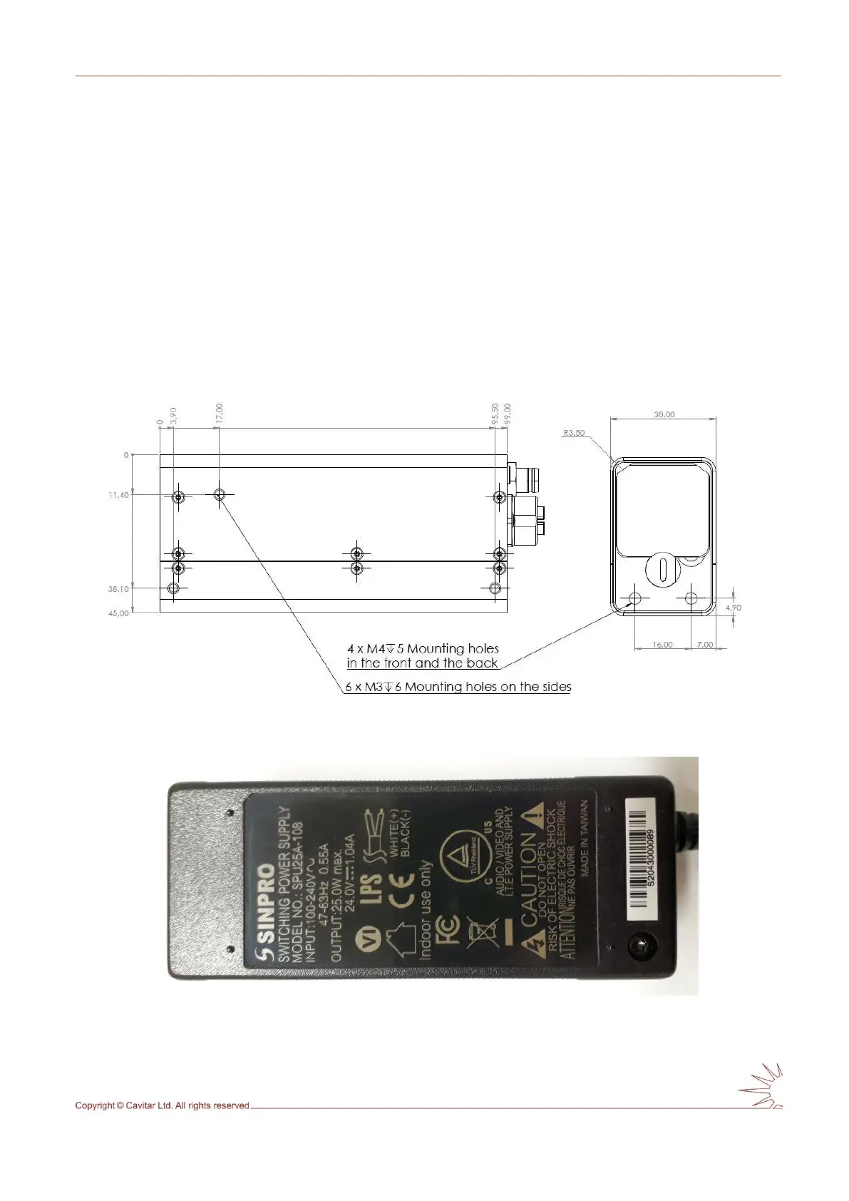
Fig. 3.5. Camera unit mechanical drawing.
Fig. 3.6. Bottom view of the power supply.