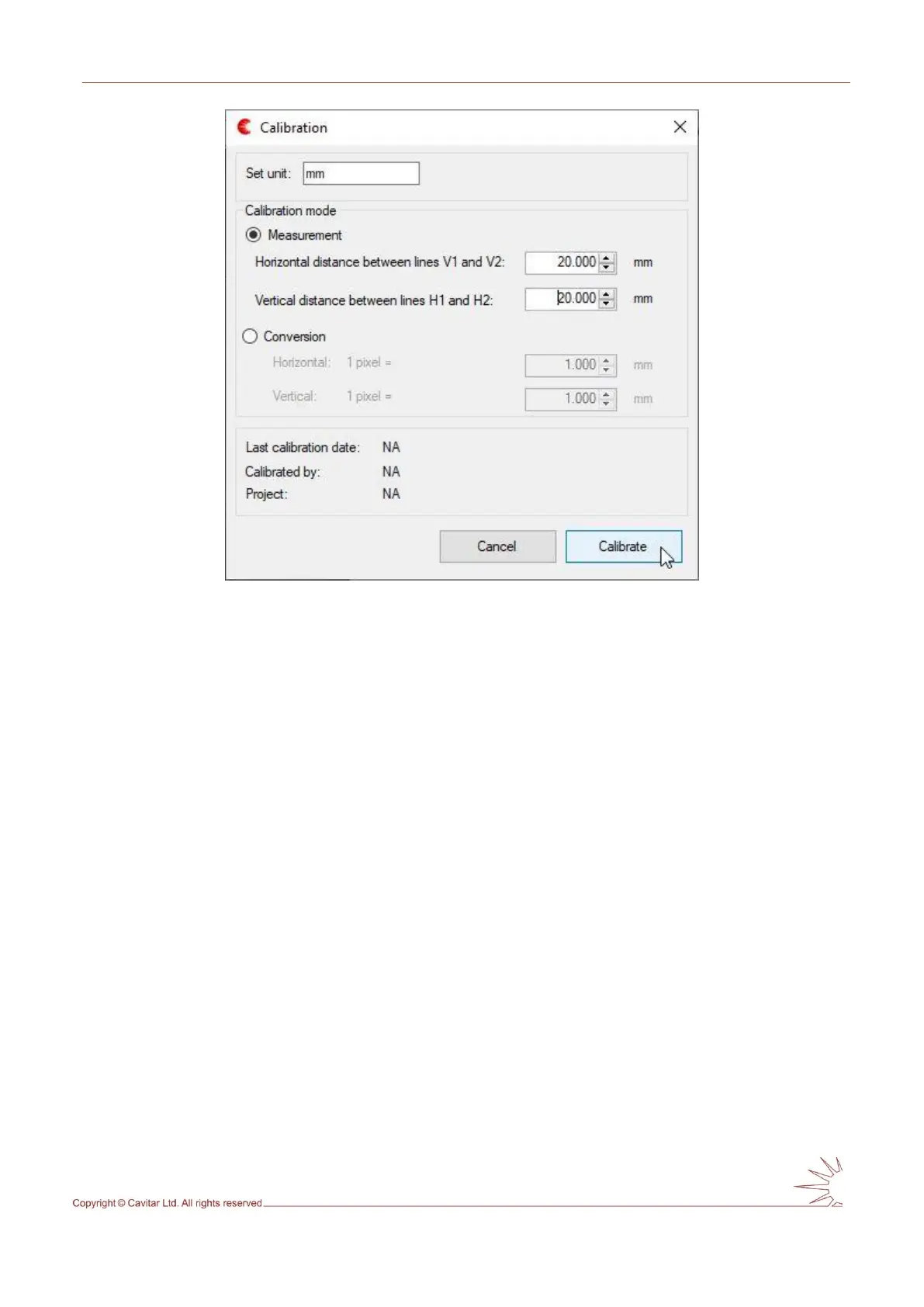
Fig. 5.18. Calibration mode window.
In calibration window the desired unit can be set (in Fig. 5.18 “mm” has been set).
Calibration can be made based on measurement (as in Fig. 5.18 above) or as a conversion.
Calibration based on measurement requires that two vertical and two horizontal guidelines
have been placed to their correct positions (e.g. according to a precise calibration pattern or
some other object with known dimensions). Once the lines are positioned to known distances
from each other, these distances are typed to the appropriate fields.
Calibration based on conversion can be made without guidelines.
In Fig. 5.17 a ruler was applied to position the vertical lines 20mm apart from each other. The
distance between horizontal lines was made equal to the distance between vertical lines (in
pixels). Therefore a value of 20 mm has been set to both horizontal and vertical distance
between lines. After pressing “Calibrate” a new window will appear (see Fig. 5.19).