22
2
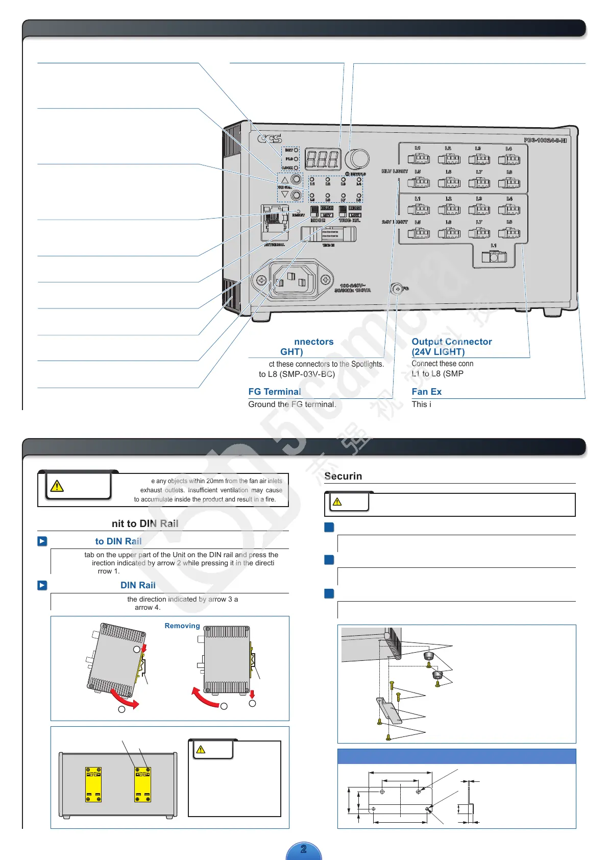
Names and Functions of Parts
Pressed with a pointed object to reset
all settings to their default values.
External Control Reset Switch
Select the channel from L1 to L8. Only the channel
on which Light Units are connected can be selected.
The channels with same channel No. of 24V LIGHT
and HLV LIGHT are operated simultaneously.
Channel Selection Switch
Used for external control with Ethernet communications.
External Control Connector
External Trigger Input Connector
Ground the FG terminal.
FG Terminal
Connect these connectors to the 24V DC Light Units.
L1 to L8 (SMP-03V-BC), L1(ELR-02V)
Output Connectors
(24V LIGHT)
Fan Air Inlet
(Left side)
This is the air inlet for the cooling fan.
Fan Exhaust Outlet (Right side)
This is the air outlet for the cooling fan.
Connect these connectors to the Spotlights.
L1 to L8 (SMP-03V-BC)
Output Connectors
(HLV LIGHT)
Setting Indicators
The indicator for the selected channel will light.
When the L1 indicator is lit, the settings for the L1 Light
Unit in the 24V Light Units (24V LIGHT) and the L1 Light
Unit in the Spotlights (HLV LIGHT) can be changed.
Channel Indicators
Press: Switches between the light intensity setting and lighting mode setting.
Press for at least 2 seconds: Locks the settings.
Rotate: Sets the light intensity or lighting mode.
Setting Switch
Displays the setting of the
light intensity or the setting of
the lighting mode.
Digital Window
Selects manual (MANU) or external (EXT) control mode.
Manual/External Mode Selector
Selects the logic of the trigger signal.
Trigger Logic Switch
Connects the power source to the Control Unit.
AC Inlet
3
Installation
Do not place any objects within 20mm from the fan air inlets
or fan exhaust outlets. Insufficient ventilation may cause
heat to accumulate inside the product and result in a fire.
1
Removing the Rubber Feet from the Bottom of the Unit
Remove the screws that hold the rubber feet in place using a Phillips
screwdriver.
2
Securing the Brackets to the Base of the Unit
Secure the Brackets to the base of the Unit with the four screws that
come with the Brackets.
3
Securing the Unit with Mounting Screws
Secure the Unit in place with mounting screws. The mounting screws must
be provided by the user.
Securing the Unit with Base Brackets
(Accessories)
* Attach the Bracket to the other side as well.
Mounting the Unit to DIN Rail
Mounting to DIN Rail
Hook the tab on the upper part of the Unit on the DIN rail and press the
Unit in the direction indicated by arrow 2 while pressing it in the direction
indicated by arrow 1.
Removing from DIN Rail
Press the Unit down in the direction indicated by arrow 3 and pull it out in
the direction indicated by arrow 4.
DIN Rail
1
2
Rear
DIN Rail
3
4
70
Two, 3.5 dia.
holes
±0.2
±0.2
59.3
29
4-C2
40
Two, 4.5 dia.
holes
195
(1)
5
10
Model: BK-PD3
Base Brackets
DIN rail brackets x 2
Screws x 8
Always use Base Brackets (model: BK-PD3) when securing the Unit at
its base. If it is secured without the Brackets, the Unit may be damaged.
Do not remove the DIN rail brackets.
If they must be removed and attached
again, make sure that you use the original
screws (or M3 × 4 mm screws).
If other screws are used, they may
short-circuit internal components and
electric shock may occur.
Caution
WARNING
Mounting Removing
BRT lit: The light intensity can be set.
PLS lit: The lighting mode can be set.
LOCK lit: The settings are locked.
Inputs the ON/OFF signal for ON/OFF Mode.
Inputs the trigger signal for Strobe Mode.
Rubber foot
Installation screw holes
(Insert the screws to a depth of no more than 5 mm
and use a tightening torque of 0.3 N·m max.)
M3 screws for the rubber feet
Screws for securing the Brackets to the mounting surface
(Prepare the mounting screws yourself according to the installation conditions.)
M3 screws for mounting the Brackets (included with the Brackets)
Holes for the mounting screws (4.5 dia.)
Caution
Includes two Base Brackets and
four mounting screws (+ one spare screw)

 Loading...