66
8
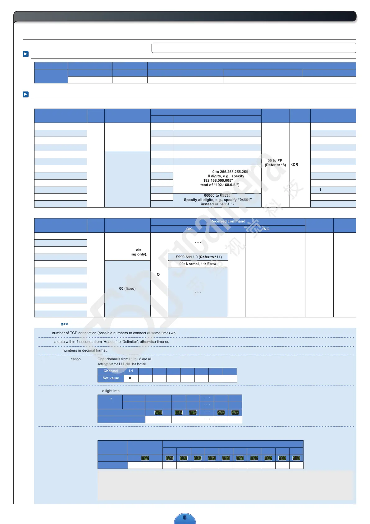
Control with External Signals
Specifications for External Control
Ethernet
RFC793, RFC768
RFC791
IEEE802.3, IEEE 802.3u, IEEE 802.3x 10BASE-T, 100BASE-TX
Specification
Communications Specifications
(*1)
Command Formats
OK
<CR><LF>
NG
O
00 to FF
(Refer to *8)
Receive Data
(*10)
Send Data
(*2)
Light Intensity Setting
Lighting Mode Setting
ON/OFF Setting
Setting Status Check
Error Status Check
All Channel Initialization
IP Address
Subnet Mask
Default Gateway
Reply IP Address
Reception Port Setting
Reply Port Setting
F
S
L
M
C
R
E01
E02
E03
E05
E04
E06
<CR><LF>
000 to 255 (Refer to *5)
00 to 10 (Refer to *6)
0: Not lit, 1: Lit (Refer to *7)
- - -
- - -
- - -
000.000.000.000 to 255.255.255.255
(Specify all digits, e.g., specify
“192.168.000.005”
instead of “192.168.0.5.”)
00000 to 65535
(Specify all digits, e.g., specify “04561”
instead of “4561.”)
00 to FF
(Refer to *8)
000
00
(Refer to *9)
- - -
- - -
- - -
192.168.000.002
255.255.255.000
192.168.000.001
192.168.000.016
40001
30001
<< Annotation>>
*1) The number of TCP connection (possible numbers to connect at same time) which PD3 correspond is “1”
*2) Send a data within 4 seconds from 'Header' to 'Delimiter', otherwise time-out error occurs and command data will be rejected.
*3) Specify all numbers in decimal format.
*4) Channel Specification
L2 L3L1
01 0200
L5 L6L4
04 05
L7
06
L8
0703
Eight channels from L1 to L8 are allocated to the 24V LIGHT and HLV LIGHT output connectors. (The ELR-02V connector for 24V LIGHT is L1.) When L1 is selected,
settings for the L1 Light Unit for the 24V LIGHT connectors (both SMP-03V-BC/ELR-02V) and the HLV LIGHT connectors can be changed. The 8 channels can be controlled separately.
*5) Light Intensity Settings The light intensity is controlled to any of 256 levels. 000 to 255 (000: Minimum, 255: Maximum)
000
0.0 (Not lit)
0.4 (Dimly lit)
Light intensity
(%)
HLV LIGHT
24V LIGHT
001
0.4
002
0.8
254
99.6
255
100.0
0.8 1.2
99.6 100.0
Set the value to 00 to enter
Normal Mode and keep the Light
Unit lit continuously.
Set the value to 00 to enter ON/OFF Mode and turn the
Light Unit ON and OFF. The Light Units are turned ON or
OFF according to the external trigger signal input.
Select the lighting time from 01 to 10 (40 µs to 40 ms) to use a strobe light.
The Light Units are turned ON for the set time after the external trigger
signal is input. The Strobe Mode can be set for 24V DC Light Units only.
*6) Lighting Mode Settings Select the lighting mode form Continuous Mode, ON/OFF Mode, or Strobe Mode. The lighting time can be set in Strobe Mode.
(The Strobe Mode can be set for 24V DC Light Units only.) For details on the external trigger input, refer to 9. Inputting the External Trigger.
40μs 80μs 120μs 200μs 600μs 1ms 4ms 10ms 20ms 40ms
01 02 03 04 05 06 07 08 09 1000
* The light intensities are theoretical values.
TCP/UDP protocol IPv4 protocol
Standard Standard Standard Baud rate Transmission medium
10 Mbps/100 Mbps (Automatically detected.)
Protocol layer
(Set values that are higher than 07 are not valid.)
Channel
Set value
(Set values that are higher
than 10 are not valid.)
Strobe Mode
Digital window
Digital window
Set value
Set value
Continuous Mode
or ON/OFF Mode
Status
Function
Light Intensity Setting
Lighting Mode Setting
ON/OFF Setting
Setting Status Check
Error Status Check
All Channel Initialization
IP Address
Subnet Mask
Default Gateway
Reply IP Address
Reception Port Setting
Reply Port Setting
Function
Sent command
Instruction
Default
Data
(*3)
DelimiterChecksum
@
00 to 07
(Refer to *4)
FF: All channels
(ON/OFF setting only).
Header Channel specification
00 (fixed)
@
00 to 07
(Refer to *4)
FF: All channels
(ON/OFF setting only).
Header Channel specification
00 (fixed)
Received command
DelimiterChecksum
N
- - -
- - -
F999.S99.L9 (Refer to *11)
01: Command error
03: Set value out of range error
02: Checksum error
00: Normal, 11: Error
ABCDEFGHIJKLMNOPQRSTUVWXYZ 0123456789
Sample of Alphanumeric Characters:
Continuous Mode ON/OFF Mode
(If the external trigger is not used, the Light Units are ON continuously.)
Strobe Mode
(If an external trigger is not used, the Light Units are OFF.)

 Loading...