33
Firmly insert the connector of the LAN cable.
1
2
Press the lock and pull out the connector.
4
Connections
1
Connect the LED Light
Connect the connecting cable to the LED Light Unit to the output connector on the Control Unit.
Connect 24V DC Light Units to the 24V LIGHT output connectors, and Spotlights to
the HLV LIGHT output connectors. One of the 24V LIGHT output connectors is an
ELR-02V connector for a High-output Light Unit.
Insert the connector to the Light Unit all the way in.
Press the lock and pull out the connector.
SMP-03V-BCSMP-03V-BC
ELR-02VELR-02V
2
Connect the AC Cord
The AC cord that is included with the Unit is for 100 to 120V AC. We recommend using the
following for 200 to 240V AC. Cable: GTCE-3 x 1.0 mm
2
(manufactured by Kawasaki Electric
Wire Company), Connector: KS-31AY (manufactured by Kawasaki Electric Wire Company)
Connect the power cord to the Control Unit and a wall socket. The Control Unit will turn ON when
power is supplied from the main power source. When the Unit is ON, the digital window will light.
3
Connect the LAN Cable
(Provided by the user)
To perform external control, connect the LAN cable to the external control connector.
The LAN cable must be provided by the customer. (Cable length should be within 30 m
at aximum.) This product recognizes either cross-cable or straight-cable automatically
by auto-negotiation function. Please reboot the product when changing the cable.
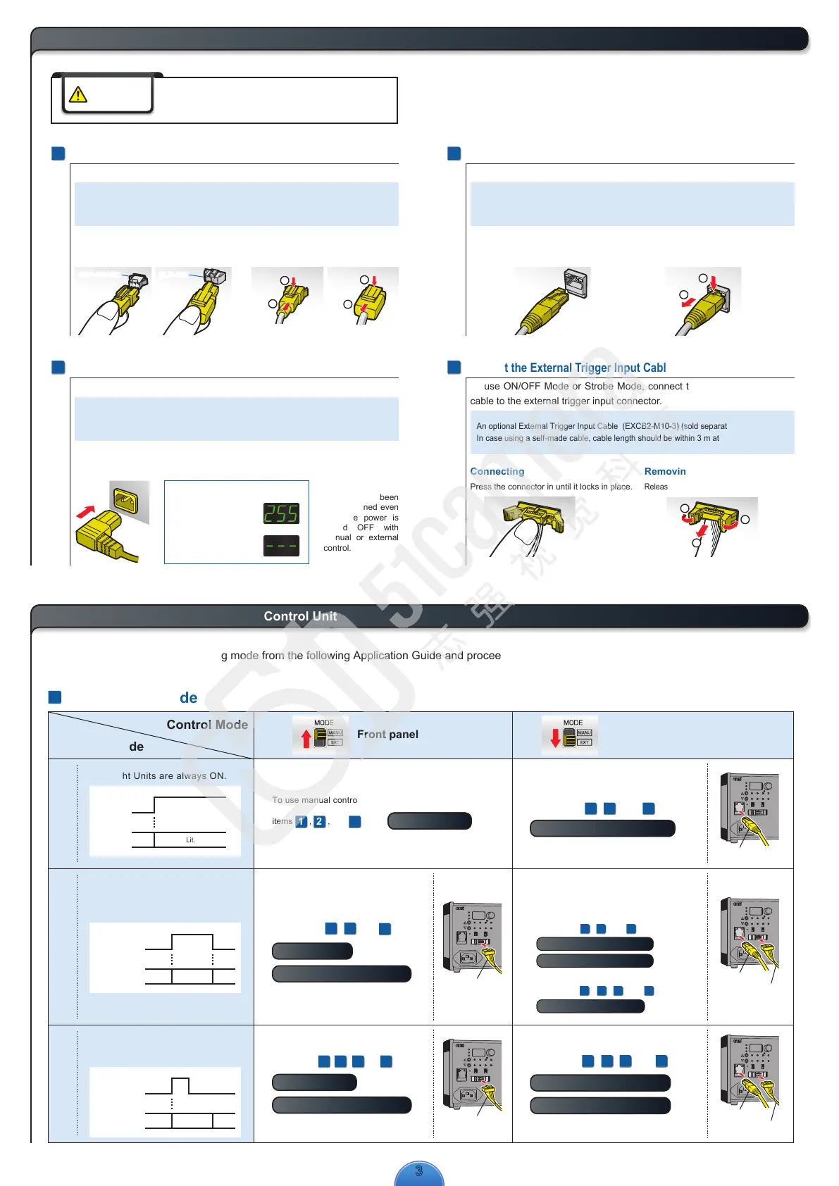
4
Connect the External Trigger Input Cable
(Optional item, sold separately)
To use ON/OFF Mode or Strobe Mode, connect the external trigger input
cable to the external trigger input connector.
An optional External Trigger Input Cable (EXCB2-M10-3) (sold separately) is available.
In case using a self-made cable, cable length should be within 3 m at maximum.
Press the connector in until it locks in place.
Release the lock and remove the connector.
Digital Window
The light intensity of the
lowest channel is displayed.
(Display when no Light
Unit is connected)
1
2
1
2
Connect the AC power cord to the AC inlet and a wall socket.
Before connecting the Control Unit, make sure that the main
power source is turned OFF. Making connections with the
power turned ON may result in a fire or electric shock.
WARNING
Connecting Removing
Connecting Removing
Connecting Removing
*Data that has been
set is retained even
after the power is
turned OFF with
manual or external
control.
Select the control mode and lighting mode from the following Application Guide and proceed to the indicated reference items.
The Light Units are always ON.
Power ON
Power OFF
Lit.Not lit.
Control Mode
Lighting Mode
Application Guide
To use external control in Continuous Mode,
refer to items , , and under
.
1 32
8
Control with External Signals
To use manual control in Continuous Mode, refer to
items , , and under .
7
Manual Control
1 32
To use manual control in ON/OFF Mode,
refer to items , , and under
and
.
7
Manual Control
1
3
2
9
Inputting the External Trigger
The Light Units are turned ON for
a set time after the external trigger
signal is input.
Photocoupler OFF
Photocoupler ON
Lit. Not lit.Not lit.
* When the Trigger Logic
Switch is set to HIGH
Continuous ModeON/OFF Mode
Strobe Mode
Front panel operation
External control using a PLC
or image process device
The Light Units are turned ON or
OFF according to the external
trigger signal input.
Photocoupler OFF
Photocoupler ON
Lit. Not lit.Not lit.
* When the Trigger Logic
Switch is set to HIGH
5
What You Can Achieve with This Control Unit
* It is possible to turn LED light unit ON and
OFF by Ethernet communications, too.
External trigger signal or Ethernet
communications setting can be selected when
using ON/OFF mode by external control.
To use external trigger signal in ON/OFF mode,
refer to items , , and under
8
Control with External Signals
9
Inputting the External Trigger
1 2 3
and
.
To use Ethernet communications setting in ON/OFF mode,
refer to items , , , and under
1 2
8
Control with External Signals
3
5
.
To use manual control in Strobe Mode,
refer to items , , and under
and
.
9
Inputting the External Trigger
7
Manual Control
1 3 42
(Only 24V DC Light Units can be set.) (Only 24V DC Light Units can be set.)
To use external control in Strobe Mode,
refer to items , , , and under
and
.
1 3 42
9
Inputting the External Trigger
8
Control with External Signals
External Trigger Input Cable
(EXCB2-M10-3)
External Trigger Input Cable
(EXCB2-M10-3)
LAN cable
LAN cable
External Trigger Input Cable
(EXCB2-M10-3)
LAN cable
External Trigger Input Cable
(EXCB2-M10-3)
1
2
1

 Loading...