5] WIRING DIAGRAM
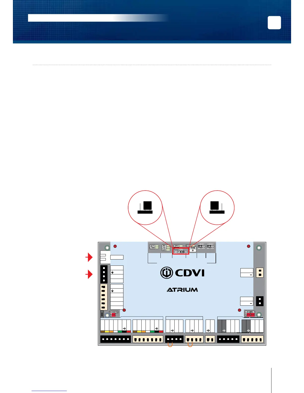
The exibility of the A22POE module allows it to be set either as a 2-door controller or 2-door expander.
Simply adjust the “TYPE” jumper to the required position (see the diagram below).
By default, each A22POE is set as a 2-door controller.
• One A22POE set as a controller can manage (be connected to) up to four A22POE modules set as
expanders for a total of 10 doors.
• To communicate with an A22POE set as a controller, use the RJ45 Ethernet connection.
• Communication between an A22POE controller and A22POE expansion modules is achieved using
the RS485 Local Bus.
INPUTS/
OUTPUTS
RS485
LOCAL
BUS
BATTERY
(12V DC)
INPUT
POWER
SUPPLY
ETHERNET
LOCAL
BUS
STATUS
LOCK 1
SETTING
LOCK 2
SETTING
READERS INPUTS
LOCKS
A22
2-Door Web-Based IP Module
DOOR 1
DOOR 1
DOOR 2
DOOR 2
DOOR 1 DOOR 2
DATA 1
Red LED 1
Green LED 1
Buzzer 1
DATA 0
+12V DC
DATA 1
Red LED 2
Green LED 2
Buzzer 2
DATA 0
+12V DC
Com. Relay 1
N.O. Relay 1
N.C. Relay 1
Lock output 1
Com. Relay 2
N.O. Relay 2
N.C. Relay 2
Lock output 2
Door Contact 1
REX 1
+12V DC
Door Contact 2
REX 2
+12V DC
Tamper Switch
+24V DC
-
+12V DC
-
+12V DC
A+
B
-
Input 1
Input 2
Output 1
+12 V DC
Output 2
ETHERNET
24V DC INPUT
BATTERY
MODULE TYPE
SYSTEM STATUS
Module Type Jumper Setting
(Controller or Expander)
EX CTEX CT
or
Module is set as a
“2-Door Controller”
(Default Setting)
Ethernet connection
when the module type is
set as a “2-Door Controller”
RS485 Local Bus connection
when the module type is
set as a “2-Door Expander”
Module is set as a
“2-Door Expander”