EN
PROFIL100EC
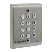
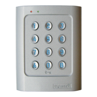
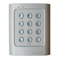
Keypad PROFIL100EC
4 cdvigroup.com
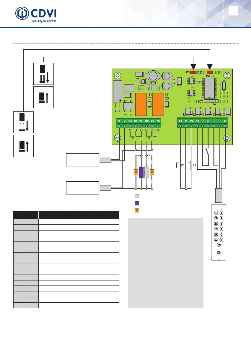
5] WIRING DIAGRAM
D - 693: Remote electronics
P3 jumper allows to the
user to modify its own
Pin code. To enable this
feature put the jumper on.
(see Programming section
in the instruction manual)
P2 jumper resets the keypad
to factory default values. Remove
thepowerfrom thekeypadthenput
the jumper. (see Programming section
in the instruction manual)
Failsafelock
Fail secure lock
Varistor
Input voltage
12 to 24V ac
or 12 to 48V dc
Power supply
According to lock
specications
Relay
1
Relay
2
Outputs Description
V
Input voltage 12V to 24V ac or 12V to 48V dc
V
Input voltage 12V to 24V ac or 12V to 48V dc
R1
N/C contact relay 1
C1
Common relay 1
T1
N/O contact relay 1
R2
N/C contact relay 2
C2
Common relay 2
T2
N/O contact relay 2
P1
Request-to-exit input relay 1
M
Commonofinputs
P2
Request-to-exit input relay 2
PX
Request-to-enter input
H
Timer Contact
+
Whitewirefromkeypad
-
Brownwirefromkeypad
E
Green or Blue wire (illumination)
Request-to-Exit inputs
- P1 request-to-exit input
activates relay 1.
- P2 request-to-exit input
activates relay 2.
- Latch or toggled output.
H input can be used with
a timer to enable the
request-to-enter function.
(Press the button on the
keypad with the key logo
When the contact is open then
the request-to-enter is disabled.
When the contact is closed then
press the button with the key
logo to enter.