CEBORA S.p.A. 20
5 - ELECTRICAL DIAGRAMS
5.1
- Power source art. 965 : see file SCHE965.pdf enclosed at the end of the manual.
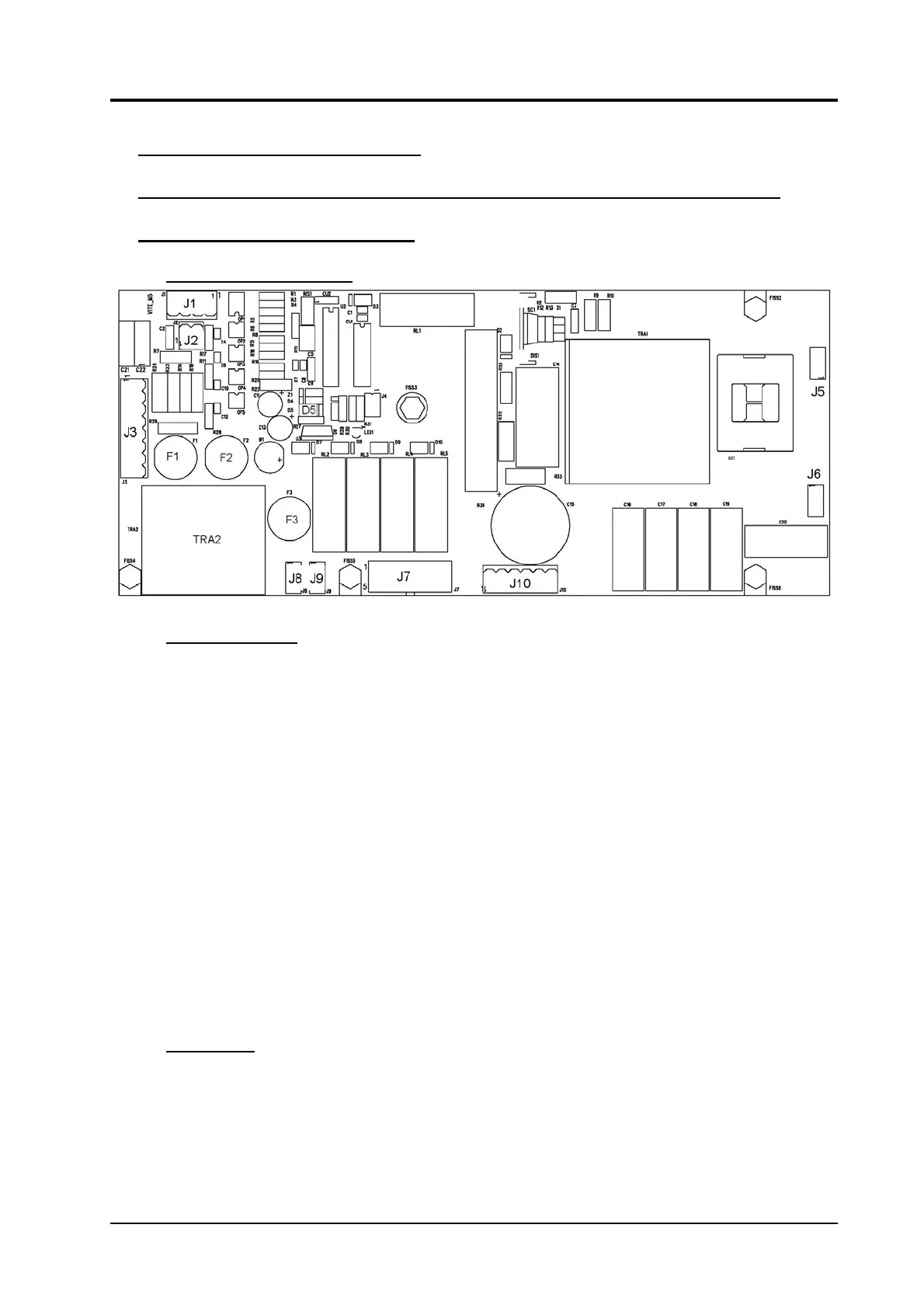
5.2 - Control board (6) code 5.602.170.
5.2.1 - Topographical drawing.
5.2.2 - Connector table.
Connector Terminals Function
J1 1 - 2 lamp (L) command output (low pressure).
J1 3 - 4 lamp (G) command output (overtemperature).
J2 1 - 2 “transferred arc” signal input from reed (42).
J3 1 - 2 start signal input from torch button.
J3 3 - 4 - 5 pressure signal input from pressure switch (33).
J3 6 - 7 temperature signal input from thermostats on transformer (44).
J4 - NU.
- J5 - J6 output for HF transformer (31).
J7 1 - 7 230 Vac input for control board (6) power supply.
J7 2 - 8 230 Vac output to control solenoid valve EL2 (34).
J7 3 - 9 230 Vac output to control contactor TLP (30).
J7 4 - 10 230 Vac output to control solenoid valve EL1 (34).
J7 5 - 11 NU.
- J8 - J9 230 Vac output for fan (39) power supply.
J10 1(+) - 6(-) rectifier (32) output voltage signal input, for HF generator power supply.
J10 3 torch nozzle voltage input.
5.2.3 - Fuse table.
Fuse Value Function
F1 0,2 A. torch start button insulated circuit power supply.
F2 0,2 A. control board (6) internal circuits power supply.
F3 2 A. service transformer TRA2 primary circuit power supply.
3.302.173 28/07/04