After dimension acquisition in ALU mode, pressing the
buttons
1
2
you can select one of the following cor-
rection modes.
The adhesive weight application distance and diameter
are measured by means of the automatic distance and
diameter gauge.
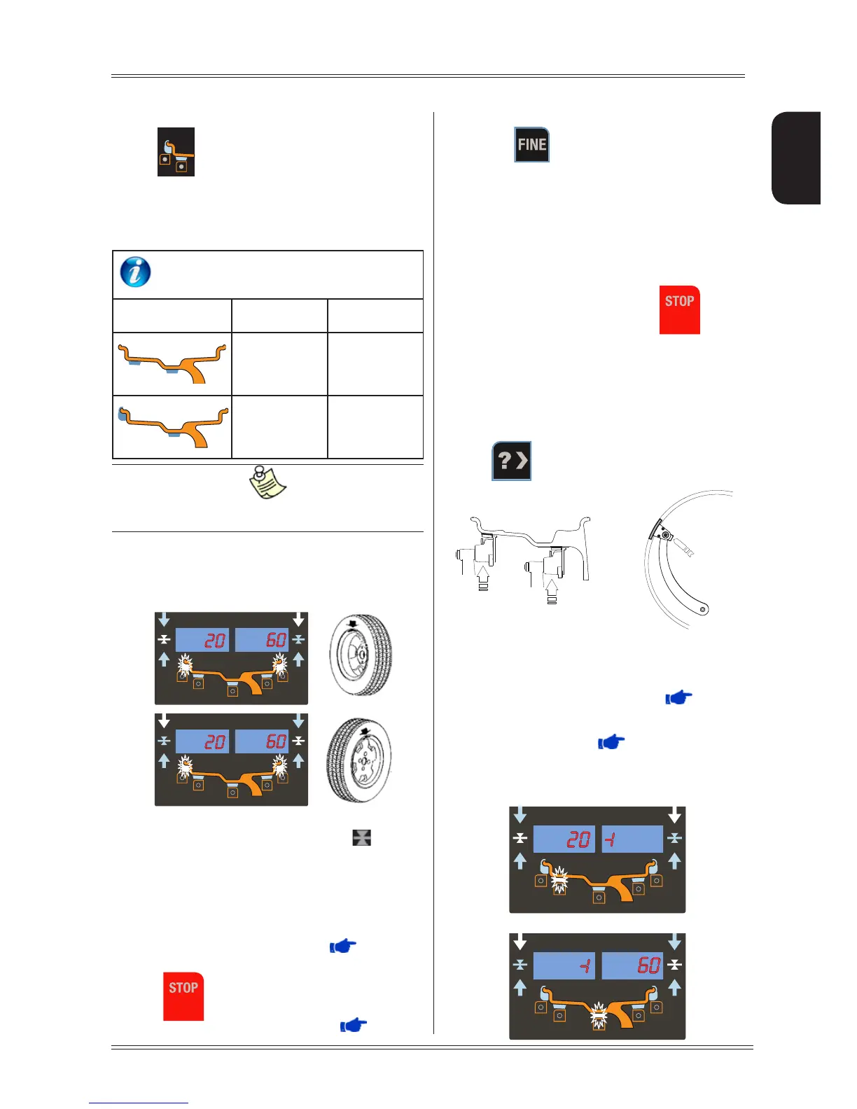
WEIGHT APPLICATION POSITION
Correction type Inside Outside
Adhesive weight
at the point
indicated by the
internal laser
Adhesive weight
at the point
indicated by the
internal laser
Clip-on weight at
12 o’clock
Adhesive weight
at the point
indicated by the
internal laser
If the laser is disabled, all the weight application positions
are at 12 o’clock.
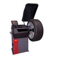
5.2 MEASUREMENT RESULT
After performing a balancing spin, the unbalance values
are shown on the displays 1-2. The symbol
indicates
the correct angular position of the wheel in order to apply
the counterweights (12 o’clock for clip-on weights; 6 o’clock
with laser indication for adhesive weights to be applied
inside the rim). In this case, the rim interior light (if ena-
bled) stays on to facilitate rim cleaning and subsequent
application of the correction weights.
If the wheel clamp option is enabled (
MENU), the
wheel is automatically clamped in the correction position.
Pressing
the chuck can be locked/released in any
position to facilitate mounting the wheel (
MENU).
If the unbalance is within tolerance, 0 (zero) is display-
ed; pressing
, you can read the values below the
required tolerance threshold.
5.3 WHEEL LOCKING
The wheel is automatically locked when reaching the correct
angular position for weight application on the inside and
outside, turning it slowly by hand. To unlock the wheel, turn
it hard to move it from the correct correction position.
If the unbalance is within tolerance, the wheel is not
automatically locked. By pressing the
button it
is possible to lock/release the spindle in any position to
facilitate the wheel assembly.
5.4 EXACT POSITIONING OF THE ADHESIVE
WEIGHT BY MEANS OF THE GAUGE WITH
CLIPS
▪ Press if using the correction method with adhe-
sive weights on the inside of the rim
▪ Fit the correction weight in the specific gauge seat with
the adhesive part facing upwards
▪ Bring the wheel into correct angular position for the
plane to be corrected
▪ If the wheel clamp option is enabled ( MENU),the
wheel is automatically clamped in the correction position.
▪ Pull out the gauge until a correction weight lights up
If the buzzer is enabled ( MENU), the attainment
of the weight application distance is accompanied by
a beep.
- INSIDE CORRECTION POSITION
- OUTSIDE CORRECTION POSITION