8
ENGLISH
B500
NR 13AJ002
RESET
SW:S1J41AH
Fm = 60.0 kN
Fp = 24.5 kN
F
m = 6.75 ton
Fp = 2.75 ton
P
m = 661 bar
Pp = 312 bar
1000
-19000
BATTERY
3 SEC.
ERROR
Fm = 60.0 kN
Fp = 58.3 kN
P
m = 661 bar
P
p= 485 bar
F
m = 60.0 kN
OK
P
m = 661 bar
OK
P
m = 9587 psi
Pp = 4525 psi
002
003
BATTERY
004
LED
ON
LED
ON
max.
BATTERY BATTERY
min.
B500
NR 13AJ002
RESET
SW:S1J41AH
Fm = 60.0 kN
Fp = 24.5 kN
F
m = 6.75 ton
Fp = 2.75 ton
P
m = 661 bar
Pp = 312 bar
1000
-19000
BATTERY
3 SEC.
ERROR
001
20001
BATTERY
Fm = 60.0 kN
Fp = 58.3 kN
Pm = 661 bar
Pp= 485 bar
Fm = 60.0 kN
OK
Pm = 661 bar
OK
Pm = 9587 psi
Pp = 4525 psi
002
003
BATTERY
004
LED
ON
LED
ON
max.
BATTERY BATTERY
min.
B500
NR 13AJ002
RESET
SW:S1J41AH
Fm = 60.0 kN
Fp = 24.5 kN
F
m = 6.75 ton
Fp = 2.75 ton
P
m = 661 bar
Pp = 312 bar
1000
-19000
BATTERY
3 SEC.
ERROR
001
20001
BATTERY
Fm = 60.0 kN
Fp = 58.3 kN
P
m = 661 bar
Pp= 485 bar
F
m = 60.0 kN
OK
P
m = 661 bar
OK
P
m = 9587 psi
Pp = 4525 psi
002
003
BATTERY
004
LED
ON
LED
ON
max.
BATTERY BATTERY
min.
NOTE: To display the momentary force or pressure
during the work cycle, select the appropriate display
from the menu (Ref. to § 4). When the operating
button is released before the motor stops automati-
cally, the display will show the peak force (Fp) or the
peak pressure (Pp) reached at that instant.
To complete the work, press the operating button again until the motor stops automati-
cally; the display will show the maximum force or pressure reached followed by "OK" to
conrm correct operation.
The display "ERROR", combined with a beep and the LEDs ashing,
indicates an incorrect crimping procedure caused by the work
cycle being interrupted before the control parameters (force/pressure)
of the tool are reached.
This error appears when the pressure release button has been operated and the tool has
already reached a pressure >100 bar. In this case, repeat the compression by pressing and
holding the operating button until the motor stops automatically.
2.4) Release of dies
By operating the pressure release button (5) (Ref. to Fig. 4), the ram will retract and open
the dies.
2.5) LED Worklights
Whilst the tool is in operation, the compression area is illuminated by two high luminosity
LED Worklights that switch o automatically at the end of the cycle.
The LED Worklights can be disabled by following the procedure described in § 4.2.
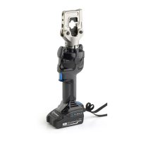
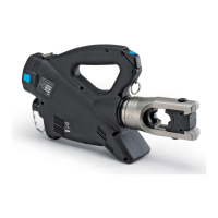
2.6) Head rotation
For ease of operation, the tool head can rotate through 180°, allowing the operator to
work in the most comfortable position.
Do not attempt to rotate the head when the hydraulic circuit is pressurised.
2.7) Capacitive touch button for menu selection
This button is located under the display and allows selection of
various screens (Ref. to § 4); it only works when the display is on.
Wearing gloves or using other objects may inhibit the operation of
the button, therefore use a bare nger to apply only a light touch.
Do not apply pressure to or stab at the touch button, a light touch using a bare
nger is sucient. The command pulse is sent when the nger releases the button.
 Loading...