32
ENGLISH
f2) To replace the microswitch
I
, first remove the
eight screws and the brake enclosure shield
ds
taking care not to damage the coupling joints.
Then, disconnect the brake power cables (mar-
ked BA1, BA2) and the micro-switch power
cables (marked BM1, BM2) from the terminal box
M
. If present, remove the encoder (see F1). Then
disassemble the brake cover enclosure
dt
and
the micro-switch
I
that is set on the external cir-
cumference of the electro-magnet.
Follow the directions in reverse order to connect
the micro-switch, the brake and the encoder, if
present.
G) Final reassembly
Remount the brake cover enclosure and the brake
cover with the relative fixing screws, taking care to
grease the coupling joints lightly beforehand.
Proper functioning of the brake can only be
guaranteed if original spare parts are used.
The air gap must be regulated at 0.3-0.4 mm.
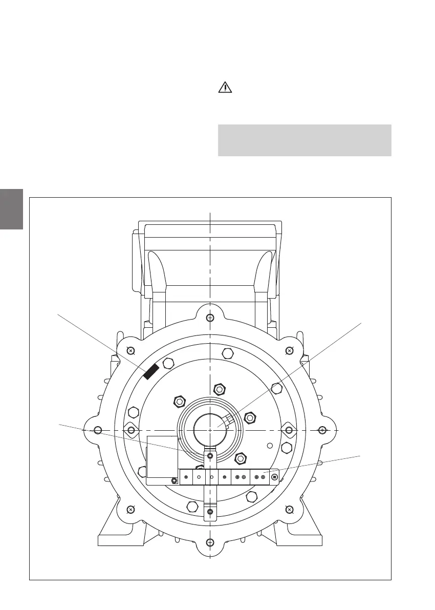
4.7 Adjusting the air gap
motors 180÷315
Fig. 4D