25
ENGLISH
Position
A
Standard position of the release lever
Position
B
Alternative position of the release lever
(optional on request)
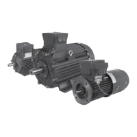
Fig. 2F
The braking unit is secured to the brake holder shield
ct
with eight fixing screws
es
.
A pinion (toothed hub)
dq
is coupled to the motor
shaft. The brake disc
dm
is fitted on the toothed hub.
The brake disc and the toothed hub, connected to
the shaft, make up the rotating part of the brake.
The brake disc can move along the axis of the too-
thed hub in order to move towards the brake holder
shield. The brake holder shield and the mobile arma-
ture
dl
make up the braking surface.
The electro-magnet
dp
is inserted into the braking
unit, along with up to nine springs
fl
. The electro-
magnet attracts the mobile armature, allowing the
rotation of the motor shaft. The springs push the
mobile armature against the brake disc, blocking the
rotation of the motor shaft.
The three adjustment screws
et
make it possible to
adjust the braking torque.
The eight nuts
fk
A permit adjustment of the air gap
between the brake disc and the brake holder shield.
If the motor is set up for installation in verti-
cal position, the brake can present some con-
struction variations.
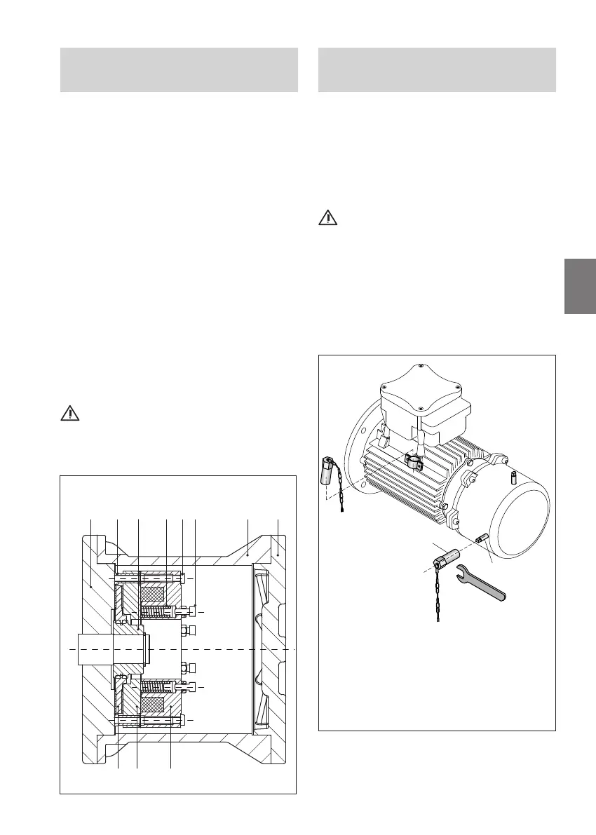
Size 71÷160 motors can be fitted with a manual
brake release lever that allows the shaft to rotate
even when the power is off.
The hand release lever
D
protrudes from the brake
cover enclosure. Use a spanner
C
to rotate the
hand release lever clockwise or anticlockwise to free
the motor shaft.
Once the end of the stroke is reached
increase the torsion slightly until the motor shaft
is released. Do not apply excessive force to the
hand release lever.
When the spanner is released the hand release lever
automatically returns to its starting position and the
brake is applied on the motor.
2.5 Manual release 71÷160
(optional on request)
2.4 Construction method for the
brake motor sizes 180÷315
dm
ct
fk
A
esfl et
dq
dt ds
dl dp
Fig. 2E
Size
180÷315