CENTER
LINE
3201 Walnut Avenue, Long Beach, CA 90807
562/426-2531
FAX 562/490-9546
Remove any protective flange covers from the valve.
Inspect the valve to be certain the waterway is free from
dirt and foreign matter. Be certain the adjoining pipeline is
free from any foreign material such as rust and pipe scale
or welding slag that could damage the seat and disc
sealing surfaces.
Any actuator should be mounted on the valve prior to
installation to facilitate proper alignment of the disc in the
valve seat.
Check the valve identification tag for materials, and oper-
ating pressure to be sure they are correct for the applica-
tion.
Check the flange bolts or studs for proper size, threading,
and length.
INSTALLATION RECOMMENDATIONS
5
Pre-Installation Procedure
1.
2.
3.
4.
5.
Personal injury or property damage
may result if the valve is installed
where service conditions could ex-
ceed the valve ratings.
WARNING!
Position the connecting pipe flanges in the line to insure
proper alignment prior to valve installation. Spread the pipe
flanges apart enough to allow the valve body to be located
between the flanges without actually contacting the flange
surfaces (See Figure 1.) Exercise particular care in handling
the valve so as to prevent possible damage to the disc or seat
faces.
Valve Installation Procedure
For Lug style valves:
a. Place the valve between the flanges.
b. Install all bolts between the valve and the mating
flanges. Hand tighten bolts as necessary.
For Check Valves:
a. Note the opening direction of the disc for proper
valve orientation.
b. Place the valve between the flanges using the four
(4) alignment holes provided.
c. Install the remaining flange bolts, shifting the valve
as necessary to permit the bolts to pass by the valve
body. Hand tighten bolts as necessary.
2.
3.
4.
5.
6.
Before completing the tightening of any bolts, the valve
should be centered between the flanges and then
carefully opened and closed to insure free, unob-
structed disc movement (See Figure 2.)
Using the sequence shown in Figure 3, tighten the
flange bolts evenly to assure uniform compression.
If an actuator is to be used, air hoses or electricity
should be connected to the unit as specified by the
actuator manufacturer.
Cycle the valve to the fully open position, then back to
the fully closed position, checking the actuator travel
stop settings for proper disc alignment. The valve
should be operated to assure that no binding is taking
place.
The valve is now ready for operation.
Remember:
Install the valve with the disc in
the “ALMOST CLOSED” position.
Do not use any flange gaskets.
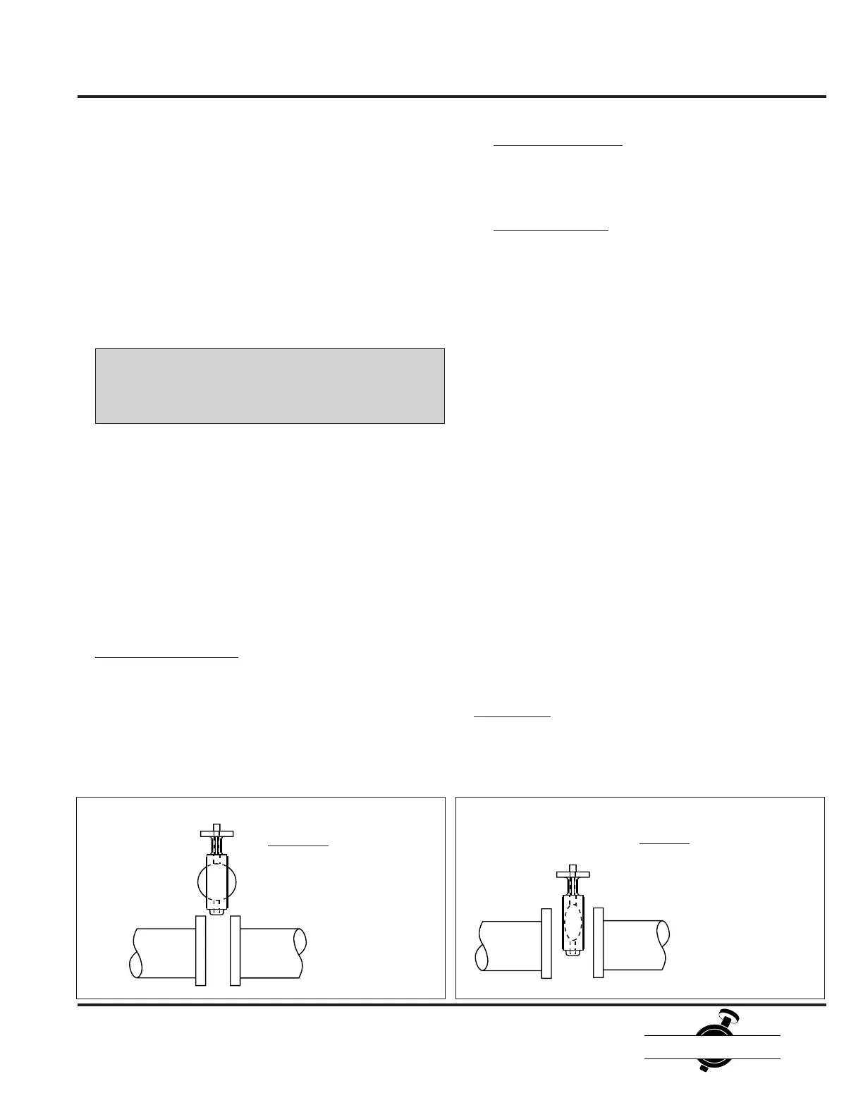
Correct
Disc positioned in the
almost closed position.
Pipe flange spread allows
sufficient room for valve.
Incorrect
Disc opened beyond valve
body face. Pipe flanges not
spread sufficiently.
Figure 1-Initial Installation of Valve
1. For Wafer style valves:
a. Place the valve between the flanges.
b. Loosely install the two upper and lower flange bolts
that pass through the body alignment holes.
c. Install the remaining flange bolts, shifting the valve as
necessary to permit the bolts to pass by the valve
body. Hand tighten all bolts as necessary.
 Loading...