CENTER
LINE
3201 Walnut Avenue, Long Beach, CA 90807
562/426-2531
FAX 562/490-9546
MAINTENANCE INSTRUCTIONS
SECTION 3
Be sure the line is depressurized and drained.
Be sure of the pipeline media. Proper care should be
taken for protection against toxic and/or flammable
fluids.
Never remove the valve without an Operator (Manual or
Automatic) already attached to the valve shaft.
Never remove the Operator from the valve while the
valve is in the pipeline under pressure.
Always be sure that the disc is in the closed position
before removing the valve.
1.
2.
3.
4.
5.
Thoroughly clean all parts. Inspect components for any
defects.
Apply a small amount of silicone grease to the inside
surfaces of the body, including the upper and lower shaft
holes.
Insert the shaft bushings into the body being careful not to
allow intrusion into the body seat bore.
Install the seat into the center of the body, making sure the
shaft holes in the seat line up with the holes in the body.
1.
2.
3.
4.
8
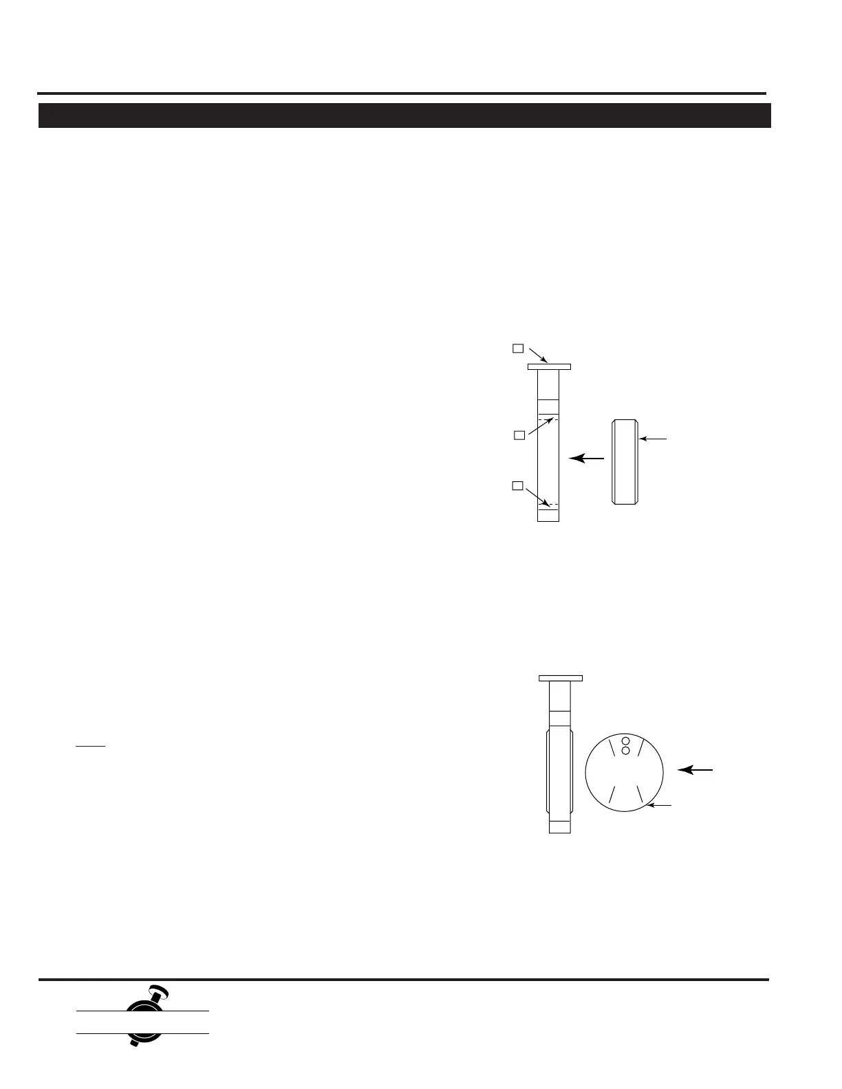
Completely coat the inside surfaces of the seat with
silicone grease. Carefully push the disc into the seat in the
open position (90 degrees to the body.) Line up the shaft
holes of the disc as close as possible with the shaft holes
in the seat body.
5.
Disc
1.
2.
3.
4.
5.
6.
Position valve flat with the disc in the closed position.
Loosen the taper pin(s) from the valve disc using a
hammer and punch.
Note: Punch should be of same size or larger
diameter as small end of taper pin to avoid mush-
rooming of taper pin.
Remove taper pin(s) from disc. Extract the valve shaft
from the body using a twisting motion.
Remove the valve disc from body making sure not to
damage the seat or disc sealing edge.
Cartridge seat removal can be accomplished from ei-
ther direction by applying pressure evenly on one face
to push the seat through the body. If the valve is of dead
end service design, remove set screws around periph-
ery of body extending into seat prior to seat removal.
Remove shaft bushings from body as required.
General Maintenance
The following periodic preventative maintenance practices
are recommended for all Center Line Butterfly Valves.
1.
2.
3.
4.
Operate the valve from full open to full closed to assure
operability.
Check flange bolting for evidence of loosening and
correct as needed.
Inspect the valve and surrounding area for previous or
existing leakage at flange faces or shaft connections.
Check piping and/or wiring to actuators and related
equipment for looseness and correct as needed.
Before removing the valve from the line or loosening any
bolts, it is important to verify the following conditions:
Butterfly Valve Assembly
Safety Precautions
Butterfly Valve Disassembly
 Loading...