CENTER
LINE
3201 Walnut Avenue, Long Beach, CA 90807
562/426-2531
FAX 562/490-9546
7
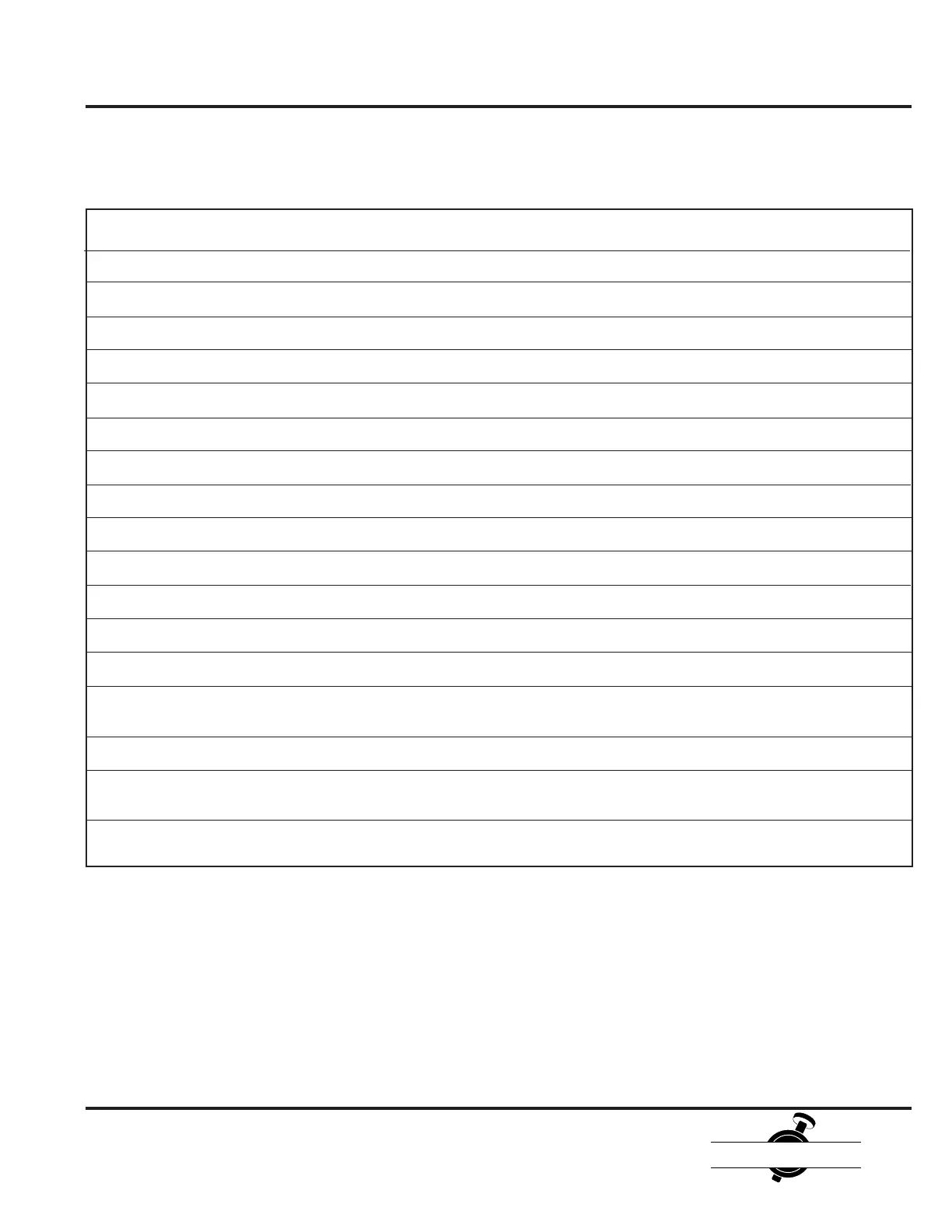
Flange Bolting Recommendations
INSTALLATION RECOMMENDATIONS
2" 5/8-11 4 4.750 5.125 1.250 15-60
2 1/2" 5/8-11 4 5.250 5.375 1.500 15-60
3" 5/8-11 4 5.250 5.375 1.500 15-60
4" 5/8-11 8 5.750 6.000 1.750 15-60
5" 3/4-10 8 6.000 6.375 1.750 25-100
6" 3/4-10 8 6.250 7.000 2.000 25-100
8" 3/4-10 8 6.750 8.000 2.250 25-100
10" 7/8-9 12 7.250 8.500 2.250 50-200
12" 7/8-9 12 7.750 9.750 2.500 50-200
14" 1-8 12 8.250 12.250 2.750 70-300
16" 1-8 16 8.750 11.750 2.750 70-300
18" 1 1/8-7 16 10.000 13.000 3.500 100-400
20" Series 200 1 1/8-7 20 11.250 14.500 4.250 100-400
20" Series 225 1 1/8-7 16 11.250 4.250 100-400
+ 4 ea. 5.000 3.250 100-400
24" Series 200 1 1/4-7 20 12.750 15.125 4.750 150-500
24" Series 225 1 1/4-7 16 12.750 4.750 150-500
+4 ea. 5.250 3.750 150-500
30" Series 200 1 1/4-7 24 13.750 4.500 150-500
+4 ea. 5.750 4.250 150-500
Center Line Wafer And Lug Valves, 2"-30", ANSI 125/150 Bolt Pattern
Valve Thread Number Stud Length Stud Length Bolt Length Req. Torque
Size Size Required Wafer B'fly (in.) Check Valve (in.) Lug B'fly (in.) (Ft-lbs)
Bolting and torque recommendations are made without a warranty, and apply only to steel weld-neck or slip-on flanges.
The use of lock washers and/or lubrication with the bolting will affect stated torque values.
 Loading...