CENTER
LINE
3201 Walnut Avenue, Long Beach, CA 90807
562/426-2531
FAX 562/490-9546
3
4
6
6
2
1
2
5
7
5
8
8
1
MAINTENANCE INSTRUCTIONS
1.
2.
3.
4.
5.
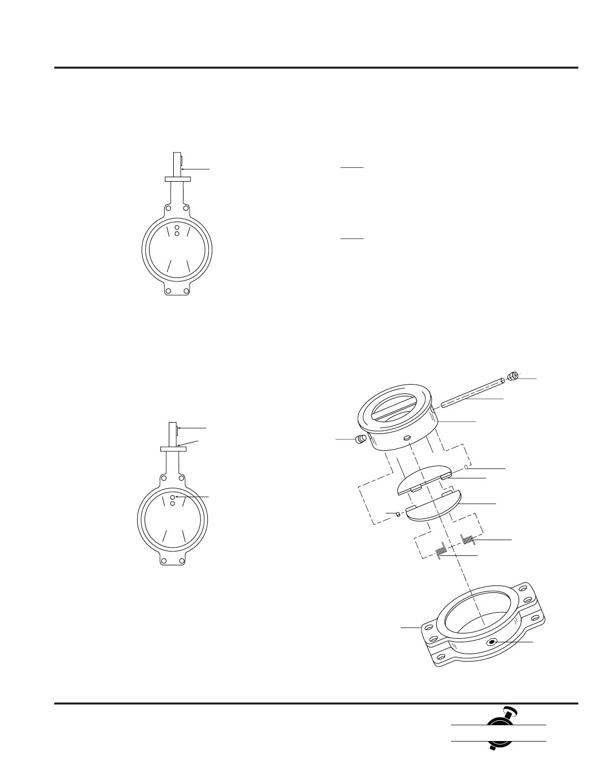
Check Valve Disassembly
Remove set screw (7) from the alignment body (1).
Remove the valve insert (4) from the alignment body (1).
Remove shaft plugs (8) from the insert with a screwdriver.
Note: Plugs are sometimes difficult to loosen. When this
happens, apply heat with small torch directly to the plug for
30 seconds. Do not allow the flame to touch the elastomer
face on either side of the inset.
Remove the shaft (3) from the valve insert.
Note: When the stem is removed, the springs (5) behind
the check plates (2) will be released. On sizes 8" to 20",
these springs must be securely held to prevent recoil upon
loss of tension.
Remove the check valve plates (2) from the valve insert.
Note the location of the thrust washers (6). These must be
replaced in the same location upon reassembly.
Butterfly Valve Assembly
(continued from page 8)
6.
7.
8.
9
Insert the shaft through the body and disc, use a twisting
motion to align the keyway parallel with the disc.
Shaft
Insert taper pin(s) into the disc and set with two or three
sharp blows. Wipe dust shield o-ring with silicone grease
and place over the shaft into the top of the body.
If the valve is of dead end service design, insert set screws
through the body into the seat.
Key
Taper Pins
O-Ring
 Loading...