Page 7H&(%$*4.8"4,7%G'*#$"&8#I%/7*,#*%4,77%JKLLLKLMMKNOPO1Item 95810
NOTICE
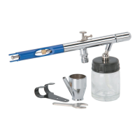
Clean the Spray Gun IMMEDIATELY after use.
Delayed or inadequate cleaning will permanently clog the Spray Gun.
D=H6BCQR6S=B?Q>@=?>B6>=>;6 D6BTR
="(%D'//7E%D*$'/
BQ%RS6!6>B%D6S?QTD%?>YTSC%HSQ@%6dR<QD?Q>-%
T#*%&87E%47*,8I%9(EI%(*3'7,$*9I%4&5/(*##*9%,"(%$&%/&)*(%$."#%$&&71%%A&%8&$%'#*%
&_E3*8I%4,(+&8%9"&_"9*I%4&5+'#$"+7*%3,#*#I%&(%,8E%&$.*(%+&$$7*9%3,#%,#%,%/&)*(%
#&'(4*%2&(%$."#%$&&71
1. Incorporate a filter, regulator with pressure
gauge, in-line shutoff valve, and quick
coupler for best service, as shown on
Figure A on page 8 and Figure B
on page 9. %=8%"8K7"8*%#.'$&22%+,77%
[,7[*%"#%,8%"5/&($,8$%#,2*$E%9*["4*%
+*4,'#*%"$%4&8$(&7#%$.*%,"(%#'//7E%
*[*8%"2%$.*%,"(%.&#*%"#%('/$'(*91%%B.*%
#.'$&22%[,7[*%#.&'79%+*%,%+,77%[,7[*%
+*4,'#*%"$%4,8%+*%47&#*9%G'"4Z7E1
>&$*-%%Do not use an automatic oiler system or
add oil to airline. The oil will contaminate the
material being propelled, ruining the final result.
2. Attach an air hose to the
compressor’s air outlet. Connect the
air hose to the air inlet of the tool.
Other components, such as a coupler plug
and quick coupler, will make operation
more efficient, but are not required.
U=S>?>Fe%%BQ%RS6!6>B%D6S?QTD%
?>YTSC%HSQ@%=;;?A6>B=<%QR6S=B?Q>-%
A&%8&$%"8#$,77%,%2*5,7*%G'"4Z%4&'/7*(%
&8%$.*%$&&71 Such a coupler contains
an air valve that will allow the air tool to
retain pressure and operate accidentally
after the air supply is disconnected.
>&$*-%%Air flow, and therefore tool performance,
can be hindered by undersized
air supply components.
3. The air hose must be long enough to reach
the work area with enough extra length
to allow free movement while working.
4. Close the in-line shutoff valve between
the compressor and the tool.
5. Turn on the air compressor according to
the manufacturer’s directions and allow
it to build up pressure until it cycles off.
6. Adjust the air compressor’s output
regulator so that the air output is enough
to properly power the tool, but the output
will not exceed the tool’s maximum air
pressure at any time. Adjust the pressure
gradually, while checking the air output
gauge to set the right pressure range.
7. Inspect the air connections for leaks.
Repair any leaks found.
8. If the tool will not be used at this time,
turn off and detach the air supply and
safely discharge any residual air pressure
to prevent accidental operation.
>&$*- Residual air pressure should not be
present after the tool is disconnected from
the air supply. However, it is a good safety
measure to attempt to discharge the tool in a
safe fashion after disconnecting to ensure that
the tool is disconnected and unpowered.
 Loading...