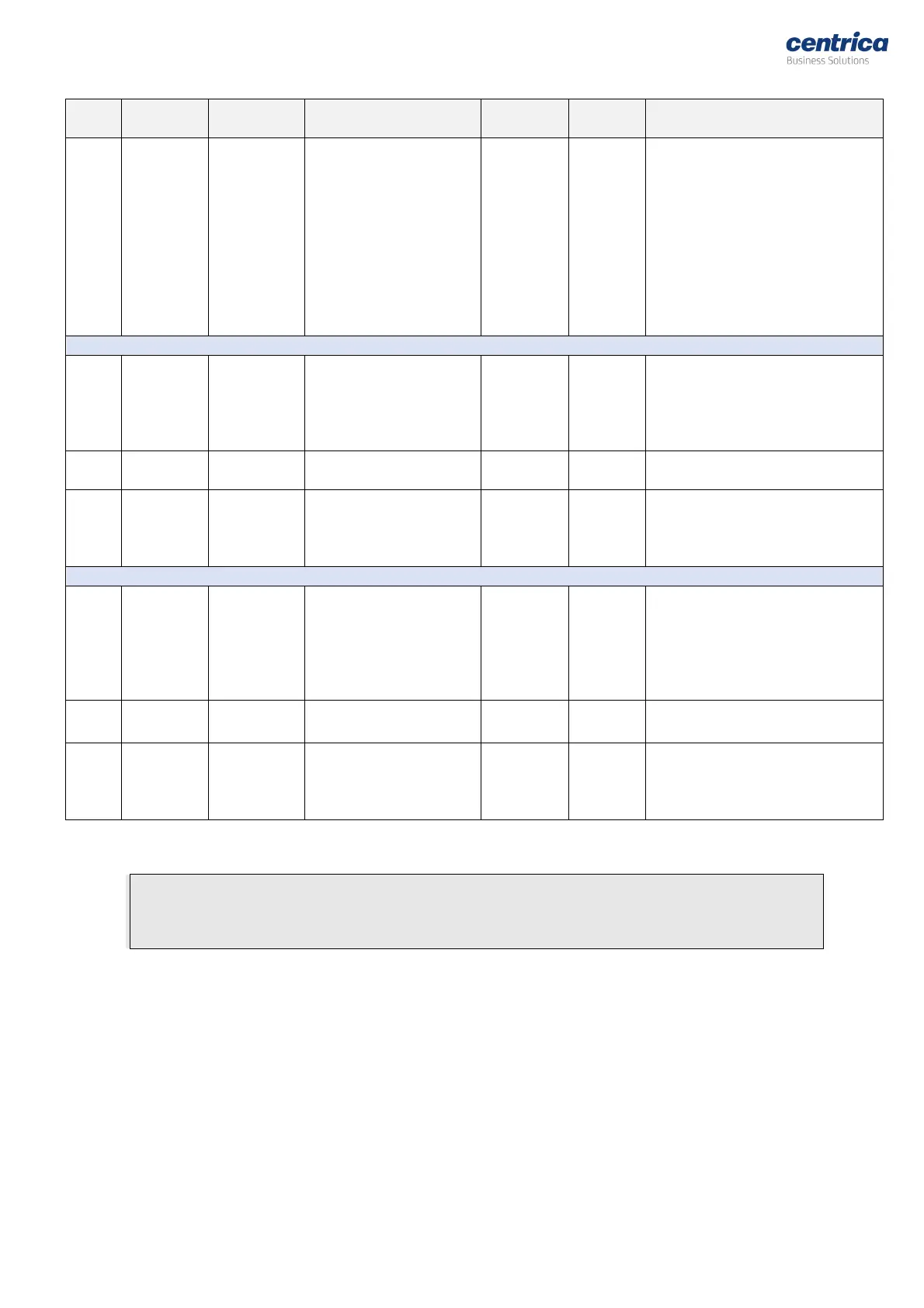
Unix Epoch SAG / SWELL
Event Timestamp
(0: There was no event
or RTC not set)
Event Timestamp – Timestamp of
the latest SAG / SWELL event
message received from the sensor.
A UNIX Epoch time is the number of
seconds that have elapsed since 00:00:00
Thursday, 1 January 1970, Coordinated
Universal Time (UTC), minus leap seconds.
The consensus is for Epoch time to be
signed, and this is the usual practice.
Nevertheless, it can be used as a 31-bit
unsigned number.
5. Pulse Counter #1 Readings
0- Disabled
1- No pulse received since last
read or reboot
2- Pulse received, No RTC
3- Pulse received, RTC is set
Unix Epoch Timestamp of
Modbus status read
Accumulated count during the
lifetime of the Bridge.
Note: the bridge counts both rising
and falling edges of the pulses.
6. Pulse Counter #2 Readings
0- Disabled
1- No pulse received since last
read or reboot
2- Pulse received, No RTC
3- Pulse received, RTC is set
Unix Epoch Timestamp of
Modbus status read
Accumulated count during the
lifetime of the Bridge.
Note: the bridge counts both rising
and falling edges of the pulses.
Table 1: Bridge Register Map
Note
: When reading or writing 32-bit elements (UINT32 or FLOAT32), it is required to access them
in a single Modbus commend (with size =2). Accessing them via two separate commands (size=1)
may create abnormal results.
Little endian
Byte swap
word order is used.
The map contains 4 main areas:
•
Bridge date/time settings
– Holding registers 1-2 - This is where the Modbus host can set
or read the
R
eal-
T
ime
C
lock of the Bridge. It can be used if there is no RTC server reachable
by the Bridge.
•
Bridge information
– Input registers 1-12 - Table 1.1 - Various Bridge status data
•
Sensor readings
– This is where the sensor readings are retrieved.
There are 3 tables with sensor readings
: (N = slot number 0 to 31)


 To Next Page