a. Table 1.2 – Input registers 2001-2010 +20N –
Sensor main readings
– An array of 32
slots x 20.
b. Table 1.3 - Input registers 3001-3004 +4N –
Extended parameters
- Array of 32 slots x 4
registers each
c. Table 1.4 - Input registers 3501-3518 +18n –
Additional parameters
– Array of 9 slots x
18 registers each (for up to 3 PAN42 sensors). Here n = 0-8 (additional_idx–1 from table
1.3)
NOTE: For the additional parameters of a PAN42 sensor, use the additional_idx from
table 1.3 to get the associated entry in table 1.4.
Additional parameters: Table 1.4(n), where n = Table 1.3(additional_idx – 1) (range 0-
8)
•
Pulse Counter #1 and #2 Readings
– These holds the counters for the two pulse inputs of
the Bridge. Tables 1.5 and 1.6 – Input registers 5001-5008 for Pulse counter #1, Input
registers 5009-5016 for Pulse counter #2.
Note: the bridge counts both rising and falling edges of the pulses. It means that for a
device with a KY output, the count should be divided by 2.
•
PAN42 EEPOROM error reports
– The PAN42 uses an EEPROM to save the energy
counters. It saves the counters every 20 seconds. In case of power shortage, when the
power is back, the last saved values are restored. If the reading from the EEPROM or
writing to EEPROM fails, the PAN42 sends an error report (error 1 or 2). The energy
counters roll over when the value exceeds the 32-bits size (0xFFFFFFFF to 0). In this case it
sends an error report 3. The user can reset the counters by pressing an internal
pushbutton (see the PAN-42 User Manual). This action sends the error report 4.
Sensor slot allocation example
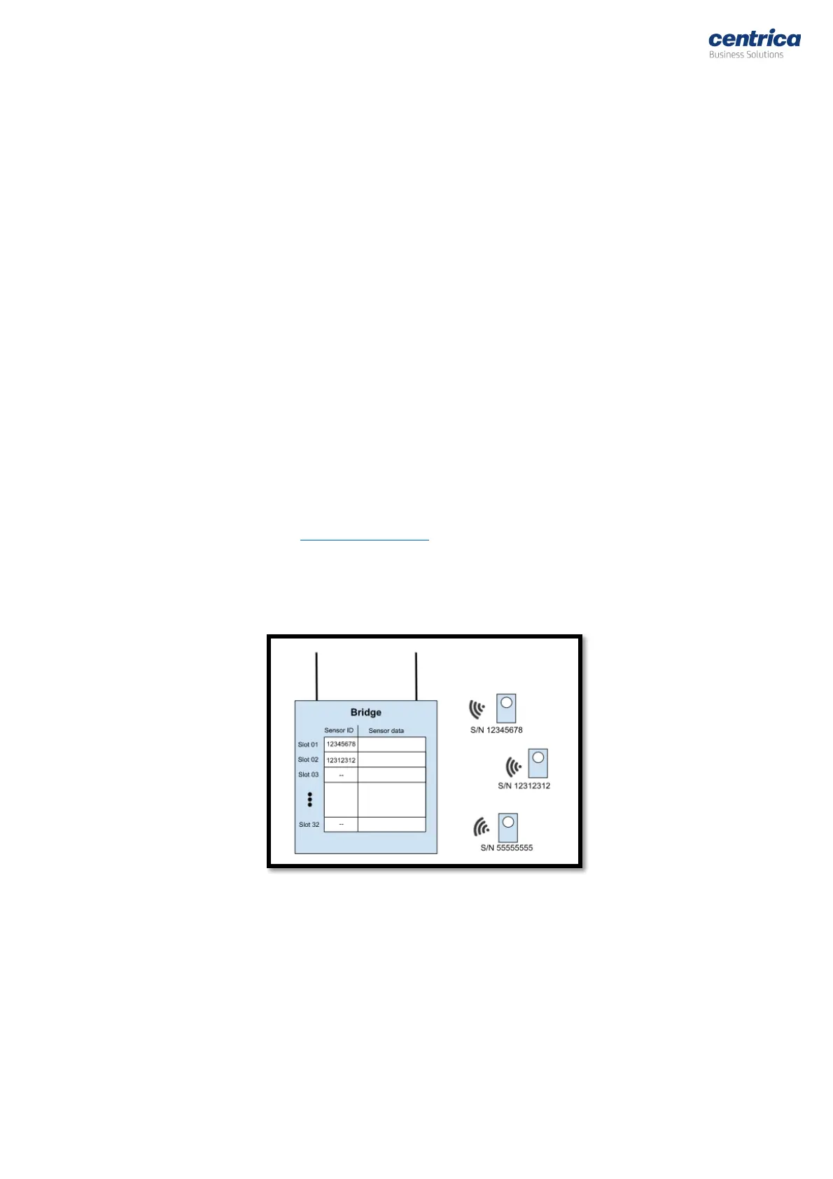
The following image depicts an example of how the sensor software model works:
Figure 2: Software model example
In the example above:
• Only two of the 32 Bridge slots have been assigned to sensors.
• Slot #1 has been assigned to sensor S/N 12345678
• Slot #2 has been assigned to sensor S/N 12312312
• Slots #3-#32 have not been assigned with any sensors and remain empty.
• Whenever a sensor message from one of the two sensors (12345678 or 12312312) is
received, the sensor-data section of the table will be updated. The update will override the
previous data.


 To Next Page