15
17.3 Connect the 2 strands on the opposite end of the cable to the terminals located on the back of the Wall
Switch.
18.1 Locate the Safety Beam Mounting Brackets provided.
18.2 Mark the inside door framing so that the bottom edge of the Mounting Brackets sit 125mm off the floor.
18.3 Use the 2 mounting screws provided to fasten each Mounting Bracket to the wall. Do not over tighten
the fixing screws as the Mounting Brackets will need to undergo adjustment at a later time.
18.4 Use the 2 screws and nuts provided to fasten the Safety Beams to the Mounting Brackets so that the
Indicator Lamp on each Safety Beam is facing upwards.
18.5 Using the twinflex cable provided, strip back and connect the 2 strands of one end of the cable to each of
the 2 terminals located on the outer cover of each Safety Beam.
18.6 Securely fix the cable up and along the wall and run one length of each cable over to the Control Box.
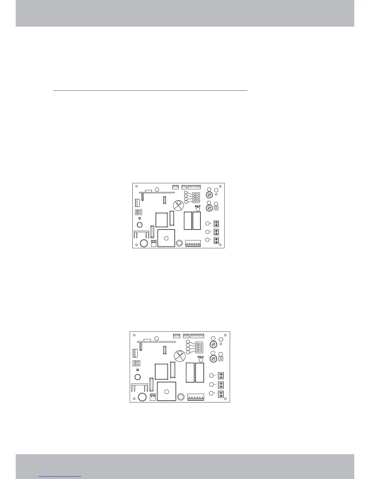
18.7 Strip back and connect one strand of each cable to the terminals marked 9B & 9C (refer to figure
below)
18.8 A green pilot light on the “emitter” will illuminate to indicate that the Safety Beams have been connected
correctly
18.9 Enable Dip Switch No.1 by selecting it to the “on” position
18.11
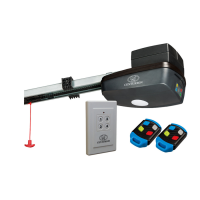
17.4 Important Note: The Wall Switch must be mounted within sight of the door and a reasonable
distance away from moving parts. It should be mounted at least 1500mm above the ground and
the Entrapment Warning Label provided must be attached adjacent to and within clear sight of it.
18.10 Important Note: For the Safety Beams to function correctly the jumper plug J8 located on the
control board (Item 12) of the RDO must be positioned so that the middle and right hand pins are
connected.
Important Note: The RDO will only support the fitment of genuine RDO Brand 2 wire Safety Beams.
(order ref: 1302BEAM01)
18. Safety Beams – Installation (Order ref: 1302BEAM01)
SETTINGS AND ADJUSTMENTS
1
2
3
4
5
6
7
8
9
11
12
9
9
10
A
B
C
1
2
3
4
5
6
7
8
9
11
12
9
9
10
A
B
C