Directional Gyro
The Heading Selector DG replaces the standard directional gyro and
provides a fully visible heading indicator around the normal DG opening.
The DG dial is marked in 5 degree intervals and numbered each 30
degrees around its azimuth. A center index is provided at the top to align
selected headings. Additional indices are located each 45 degrees to
facilitate rapid turn selection without mental arithmetic. Any heading may
be selected, either before or after engagement, and turns up to 180
degrees may be programmed directly, either right or left. If the heading
indicator is rotated beyond 180 degrees from the DG card heading, the
heading selector will command a reversal in bank to reach the resultant
selected heading in the shortest direction .
The DG card is normally set to the magnetic compass with the card set
knob on the left in the usual fashion, while the heading selector indicator
is rotated by the heading selector knob on the right. It will still be
necessary for the pilot to verify the compass card heading with the
magnetic compass periodically. Direction of rotation of both the knobs
and indicator commands the same direction of turn.
NSD-360A, NSD-1000 AND
OTHER HEADING SYSTEMS
The Century 2000 autopilot may be optionally equipped with the Century
Flight Systems, Inc. NSD-360A or NSD-1000 HSI. The explanation which
follows will be based on Century’s HSI, however the principles will apply
equally to the heading systems of other manufacturers provided the
differences in design, features and concepts are ascertained and allowed
for such as slaving, knob location, size, etc.
The NSD-360A and the NSD-1000 (Navigation Situation Display) are
basically identical units except for the gyro capsule. The 360A is an air
driven gyro where as the 1000 is an electric gyro. The HSIs have
electrically servoed heading card driven by the information processed
from the gyro capsule. Warning flags and indicators include NAV flag,
glideslope flag, TO/FROM meter and heading flag. Lateral radio
information is presented by the left/right meter and vertical radio
information is presented by the glideslope meter. Autopilot heading
information is represented by positioning the heading bug to the desired
heading track.
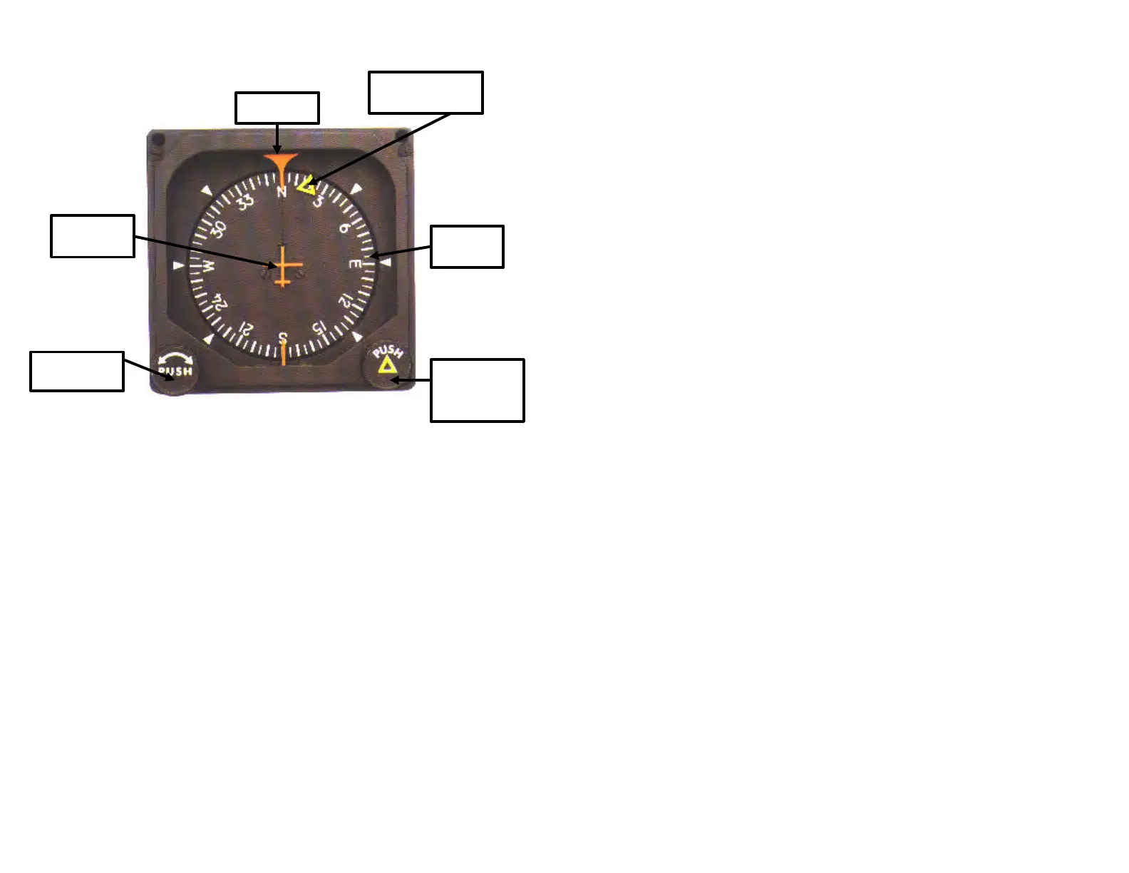
23 24
Lubber Line
Autopilot
Heading Bug
Miniature
Airplane
Heading
Selector
Knob (Push)
Card Set
Knob (Push)
Compass
Card