Do you have a question about the Certikin Genie MB50S and is the answer not in the manual?
Details on choosing a suitable location for the heater installation.
Critical safety warnings and instructions before appliance use.
Emergency procedures to follow if a gas leak is detected.
Explanation of the heater's control panel buttons, displays, and indicators.
Explains operating LEDs, fault indicators, and error codes.
Covers safety precautions, cleaning, servicing, and winterisation procedures.
Recommended chemical levels for pool water in contact with the heater.
Legal requirements and standards for gas appliance installation.
Advice on selecting and preparing the installation site.
Specifies minimum clearances for flue terminal positions.
Ensures combustion products do not re-enter the building.
Clarifies that no specific air vent is needed for the room.
Warnings and recommendations for outdoor installation.
Details on the condensate trap and pipework requirements.
Guidance on plumbing the heater with pool pump and filter.
Instructions for protecting the heater during winter.
Specifies mains connection, isolation, and cable requirements.
Minimum clearances for installation and servicing.
Step-by-step guide for installing the heater indoors.
Instructions for fitting the specific outdoor terminal.
Details on flue system parts, FEL calculation, and assembly.
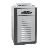
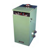
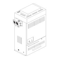
Diagrams and labels for heater dimensions and connection points.
Diagrams showing dimensions for horizontal wall flue terminals.
Diagrams for outdoor flue terminal dimensions.
Diagrams for vertical roof flue terminal dimensions.
Visual examples of different flue configurations.
Table listing available flue kit components and their FEL.
Further details on flue kit components and their Flue Equivalent Length (FEL).
Covers terminal guards, roof terminal fitting, plumbing, flow rate, and pressure switch.
Procedure for converting the heater from LPG to Natural Gas.
Instructions for connecting the gas supply, including pressure and testing.
Table showing gross heat output ratings for different models.
Options for connecting the condensate drain pipe.
Warnings and requirements for earthing and mains supply connection.
Details on using the Certikin CCP01 control unit.
Information on connecting multiple heaters using a kit.
Visual examples of condensate disposal methods.
Instructions for unscrewing and cleaning the syphon bowl.
Important points before and during heater commissioning.
Step-by-step guide for starting up and testing the heater.
Information on LPG model modifications and fault indicators.
How to enter and use the user setup mode for display settings.
Explains connecting multiple heaters for increased output and fail-safe design.
Lists part codes for multiple heater kits based on the number of heaters.
Step-by-step guide for installing the multiple heater kit.
How to operate the system with a master and slave configuration.
How the display indicates status in a multi-heater setup.
Information on wall hanging the Genie 35 and 50 models.
Step-by-step guide for mounting the heater on a wall.
Presents the electrical schematic and wire color code legend.
Key operational requirements and safety checks before electrical work.
Overview of safety controls, lockouts, and instructions for setup/service modes.
Details on service mode settings, tables, and test display modes.
Explains fault codes indicated on the front panel display and LEDs.
Details fault codes indicated by LEDs on the printed circuit board (PCB).
Guidelines for regular checks, cleaning, and component inspection.
Procedures for inspecting burner, electrodes, pipework, and seals.
Procedures for checking condensate syphon, gas rate, and combustion.
Information on replaceable parts and general warnings before work.
Detailed procedures for replacing various heater and electrical components.
Comprehensive list of spare parts with manufacturer and supplier part numbers.
Image showing the location of key electrical components.
Fields for recording installer details, working pressure, CO, CO2, and user instruction.
Section to log dates, cleaning, pressure, CO, and CO2 readings for maintenance.
| Brand | Certikin |
|---|---|
| Model | Genie MB50S |
| Category | Swimming Pool Heater |
| Language | English |