Do you have a question about the Cerwin-Vega CV-1800 and is the answer not in the manual?
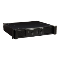
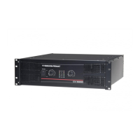
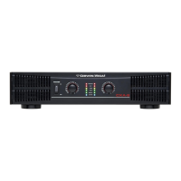
Welcome to the Cerwin-Vega CV Series professional power amplifier line, engineered for superior sound.
Provides guidance on unpacking, handling, and installing the amplifier to ensure longevity.
Highlights the power ratings, channel modes, limiter, input controls, and cooling systems.
Ears used to mount the amplifier in any standard 19" rack.
Cooling vents for the amplifier; keep unobstructed and clean.
This switch powers the unit on and off.
Blue LEDs indicate signal presence at the amplifier input.
Red LEDs indicate signal clipping or distortion, requiring gain reduction.
Blue LEDs indicate AC power connection and amplifier status.
Red LEDs indicate protect mode due to faults, muting speaker output.
21-position potentiometers adjust input level for each channel.
Variable speed cooling fan; ensure vents are unobstructed.
Balanced combo connectors (XLR/1/4" TRS) for input signals.
Jacks for sending a parallel signal to other devices or amplifiers.
Activates built-in filter rolling off signals below 40Hz.
Engages/disengages clip limiter to prevent distorted output.
Selects amplifier operating mode (stereo, bridged, parallel).
Connects speakers using bare wire, banana plugs, or spade lugs.
Connects speakers using Speakon cables for channels or bridged mode.
Acts as a fuse; trips on fault or overload, resettable.
IEC connector for the AC power cable.
Graphic and text explaining mode selection for the amplifier.
Describes independent channel operation and recommended impedance.
Explains signal amplification and output for both channels from one input.
Details strapping channels for higher power monaural output.
Diagrams illustrating speaker connections for stereo mode.
Diagrams showing speaker connections for parallel mode.
Diagrams for connecting speakers in bridged mono mode.
Explains wiring for unbalanced 1/4" connectors.
Details wiring for Speakon connectors (front and rear view).
Explains wiring for balanced TRS 1/4" connectors.
Guide for XLR balanced input and output wiring.
| Power Output | 1800W |
|---|---|
| Frequency Response | 20 Hz - 20 kHz |
| THD | < 0.1% |
| Signal to Noise Ratio | > 100 dB |
| Input Impedance | 20 kOhms |
| Damping Factor | > 200 |
| 8 Ohms Bridged | 1200 Watts |