PILOT'S
OPERATING
HANDBOOK
SUPPLEMENT
23
CESSNA
4OO
TR,ANSPONDER
AND ENCODING
ALTIMETER,
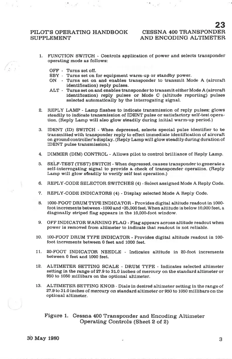
1. FUNCTION SïVITCH
-
Controls
applica,tion of
power
a,nd
selects transponder
operating mods as follows:
OFF
-
Turns sot off,
SBY - Turns set on for equipment werm-up
or standby
power.
ON
-
Turns set on and
enables transponder to
transmit
Modo A
(a,ircraft
identifica,tion) reply
pulses.
ALT
-
Turns set
on
and enables transponder to
transmit either Mode A
(aircreft
identification) reply
pulses
or Mode C
(altitude
reporting)
pulses
sele@ted
automatically
by the interrogating signal.
2. REPLY LAMP
-
Lamp flashes to indicate trensmission
of reply
pulses; glows
steadily to indica,te
transmission of IDENT
pulse
or sa,tisfectory self-test opera-
tion.
(Reply
Lamp
will
also
glow
steadily during
initial wa,rm-up
period.)
3. IDENT
(ID)
SWITCH
-
When depressed, selects
special
pulse
identifier to
be
transmitted
with
transponder
reply
to
effect immediate
identification of airolaft
on
ground
controller'sdisplay.
(Reply
Lamp will
glow
steadily
duringdura,tion of
IDENT
pulse
transmission.)
4. DIMMER
(DIM)
CONTROL
-
Allows
pilot
to control brilliance
of Reply Lamp.
5. SELF
-TEST (TEST)
SWITCH
-
When
dqpressed, causes transponder
to
generate
a
self-interrog&ting
signal to
provide
a oheck of transponder
operation.
(Reply
Lamp will
glow
s?€adily to verify self t€st operation.)
6. REPLY-CODE
SELECTOR SWITCHES
(4) -
Select assigned Mode
A Reply Code.
7. REPLY-CODE
INDICATOH,S
(4)
-
Display selected
Mode
A Reply Code.
8. 1000-FOOT
DRUM TYPE INDICATOR - Provides digital altitude
readout in 1000-
foot increments
between
-
1000
and
+3õ,000
feet. When altitude
is below lO.00O feet, a
diagona,lly
striped flag appears
in
the
10,000-foot window.
9.
OFF INDICATOR
WARNING
FLAG
-
Flag appears across altitude
rea,dout when
power
is removed
from altimeter to indioate
tha,t
readout is not reliable.
10.
100-FOOT
DRUM
TYPE
INDICATOR - Provides digital altitude
readout in 100-
foot increments
between 0 feet
and
1000
feet.
LL. ZO-FOOT
INDICATOR
NEEDLE
-
Indicates eltitude
in U0-foot
increments
between
0 foet
and
1000 feet.
12. ALTIMETER,
SETTING SCALE
-
DRUM
TYPE
-
Indica,tes selected
altimeter
setting
in the
ra,ngo
of 27.9
to 31.0
inches of mercury on the standard altimoter or
950 to 1050
mlllibars
on the optional
altÍmeter.
13. ALTIMETER,
SETTING
KNOB -
Dials in
desÍred
altimeter
setting
in the range
of
27.9 to
31.0 inches
of
mercury on
sta,ndard
altimoter o¡
9EO to 1050 millibers on
the
optional
altimeter.
Figure
1.
Cessna
400
Transponder
and Encoding Attimeter
Operating
Controls
(Sheet
2 ot 2)
3
3O
May
1980
 Loading...