EasyManua.ls Logo

Cessna 1971 Super Skymaster - Page 10

Cessna 1971 Super Skymaster
63 pages
Print Icon
To Next Page IconTo Next Page
To Previous Page IconTo Previous Page
Loading...
··Fun
rlQW
SYSTEM
INDIC_IO.
Schematic
~
I
I
11TH
lUIIUlIl
flEl
sysnl ,
L_
VA'"
1\
/'
~?i.~·
"'.
\~~)
AUX.
fUn
1'1,1/1111'
AUX
full'UIoO'
swnctt
CODE
'Ulii.
nOM
,til
MAIN TANt($
ro
~
fIIONt
lNG/In
AI«I CROSSfHD
TO
RE"R
fHGlHf.
fUH
FRO~
un
AUXILl""V
fANt( TO
UOST
tNC'N'f
ONtY.
fUEl
FRO~
~It;;ttt
MAlN 1AHI\$
TO
~
UAR
fNOINe
"NO
Cli\O$$tEfO
fO
flONT
ENGINt.
run
nO/lll
.1Gtff
---,
AUlllllA~Y
1ANI\ to n
....
(NCo'"
I
I
IID::J
VAPOR REwa...:
nO/lil
~
ANO
M'UUU
UNITS
TO
fufl
INJECTION
"IOlIlE
··fun
flOW
It'" A SINGlE
OU
...
,·INOICATING fUEl
flOW
11'0101(4101.
IS
uuo
'011:
lOTH
£NO'NlU.
INPICATQR
DD1I
=
VINf
lIHn
....
,.,
SINGtf
CONnQl
.Ormo"
nH:talcAtt't
SUVU
lOll1
.IGHl
ANP
LHI
/ll\A:N
tAHU
A
$E~ARAn
IUClllC;At
CONNECllOH
MONITOI
SHV!S
.OTH
...
UJiu,I,.,n
--=-
TANI.S .
...
CIoI_,.IC_l
CONHItCnON
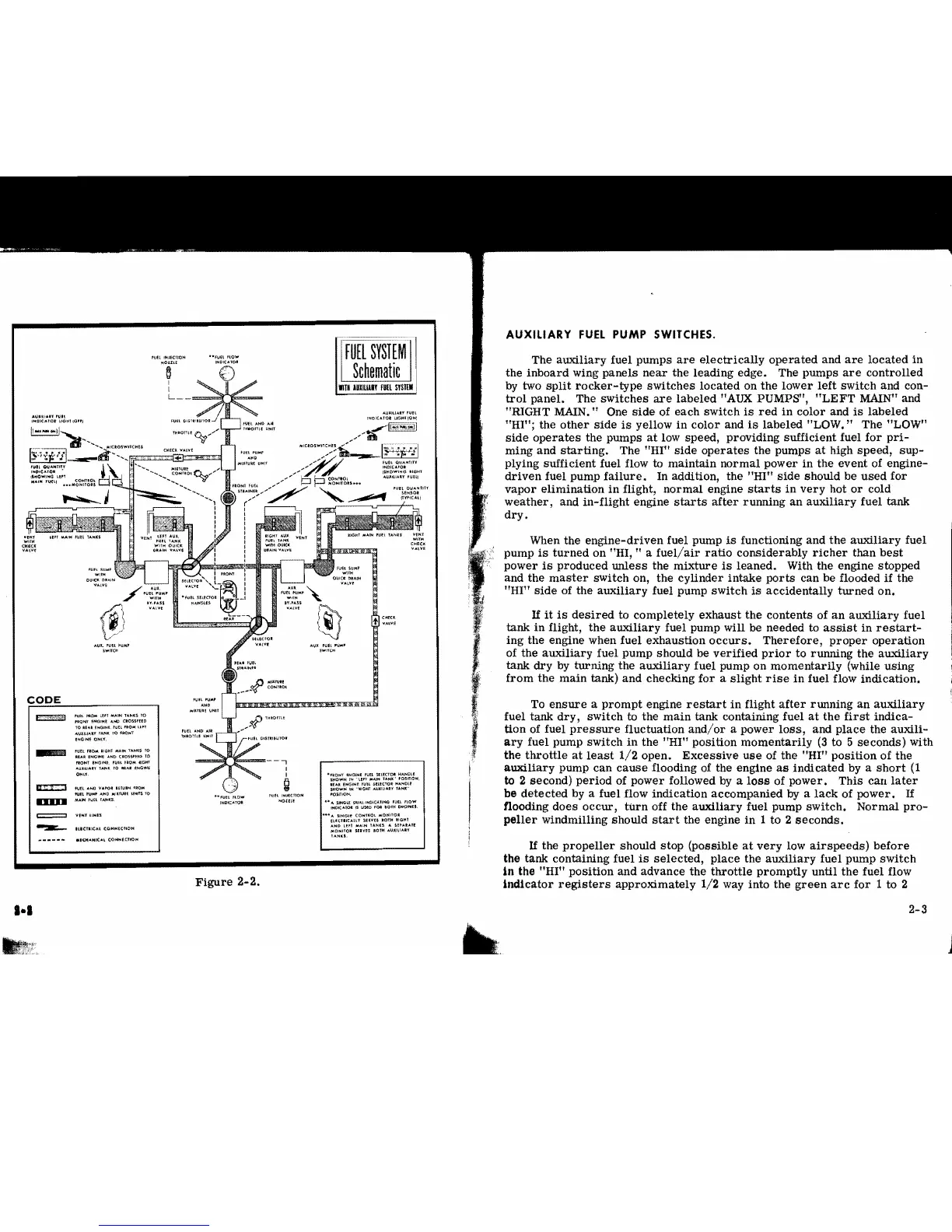
Figure
2-2.
I·a
AUXILIARY
FUEL
PUMP
SWITCHES.
The
auxiliary
fuel
pumps
are
electrically
operated
and
are
located
in
the
inboard
wing
panels
near
the
leading
edge.
The
pumps
are
controlled
by two
split
rocker-type
switches
located
on
the
lower
left
switch
and con-
trol
panel.
The
switches
are
labeled
"AUX PUMPS",
"LEFT
MAIN" and
"RIGHT MAIN." One
side
of
each
switch
is
red
in
color
and
is
labeled
"HI";
the
other
side
is
yellow
in
color
and
is
labeled
"LOW."
The "LOW"
side
operates
the
pumps
at
low
speed,
providing
sufficient
fuel
for
pri-
ming
and
starting.
The
"HI"
side
operates
the pumps
at
high
speed,
sup-
plying
sufficient
fuel flow to
maintain
normal
power
in
the
event
of
engine-
driven
fuel
pump
failure.
In addition, the
"HI"
side
should
be
used
for
vapor
elimination
in
flight,
normal
engine
starts
in
very
hot
or
cold
weather,
and
in-flight
engine
starts
after
running
an
auxiliary
fuel
tank
dry.
When the
engine-driven
fuel pump
is
functioning
and
the
auxiliary
fuel
pump
is
turned
on "HI, .. a
fuel/air
ratio
considerably
richer
than
best
power
is
produced
unless
the
mixture
is
leaned.
With the engine
stopped
and
the
master
switch
on,
the
cylinder
intake
ports
can be flooded
if
the
"HI"
side
of
the
auxiliary
fuel pump
switch
is
aCcidentally
turned
on.
If
it
is
desired
to
completely
exhaust
the
contents
of
an
auxiliary
fuel
tank
in
flight,
the
auxiliary
fuel pump will be needed to
assist
in
restart-
ing
the
engine when
fuel
exhaustion
occurs.
Therefore,
proper
operation
of
the
auxiliary
fuel
pump
should
be
verified
prior
to
running
the
auxiliary
tank
dry
by
turning
the
auxiliary
fuel
pump
on
momentarily
(while
using
from
the
main
tank)
and
checking
for
a
slight
rise
in
fuel flow
indication.
To
ensure
a
prompt
engine
restart
in
flight
after
running
an
auxiliary
fuel tank
dry,
switch
to
the
main
tank containing fuel
at
the
first
indica-
tion
of fuel
pressure
fluctuation
and/or
a
power
loss,
and
place
the
auxili-
ary
fuel pump SWitch
in
the
"HI"
pOSition
momentarily
(3
to 5
seconds)
with
the
throttle
at
least
1/2
open.
Excessive
use
of
the
"HI"
position
of
the
auxiliary
pump
can
cause
flooding of the engine
as
indicated
by a
short
(1
to
2
second)
period
of
power
followed by a
loss
of
power.
This
can
later
be
detected
by a fuel flow
indication
accompanied
by
a
lack
of
power.
If
flooding
does
occur,
turn
off
the
auxiliary
fuel pump
switch.
Normal
pro-
peller
windmilling
should
start
the engine
in
1
to
2
seconds.
If
the
propeller
should
stop
(possible
at
very
low
airspeeds)
before
the
tank
containing fuel
is
selected,
place
the
auxiliary
fuel
pump
switch
In
the
"HI"
pOSition
and
advance
the
throttle
promptly
until
the
fuel flow
Indicator
registers
apprOximately
1/2
way into
the
green
arc
for
1
to
2
2-3
~"fi'
~t::~0~.·
...