3
INSTALLER’S INSTRUCTION
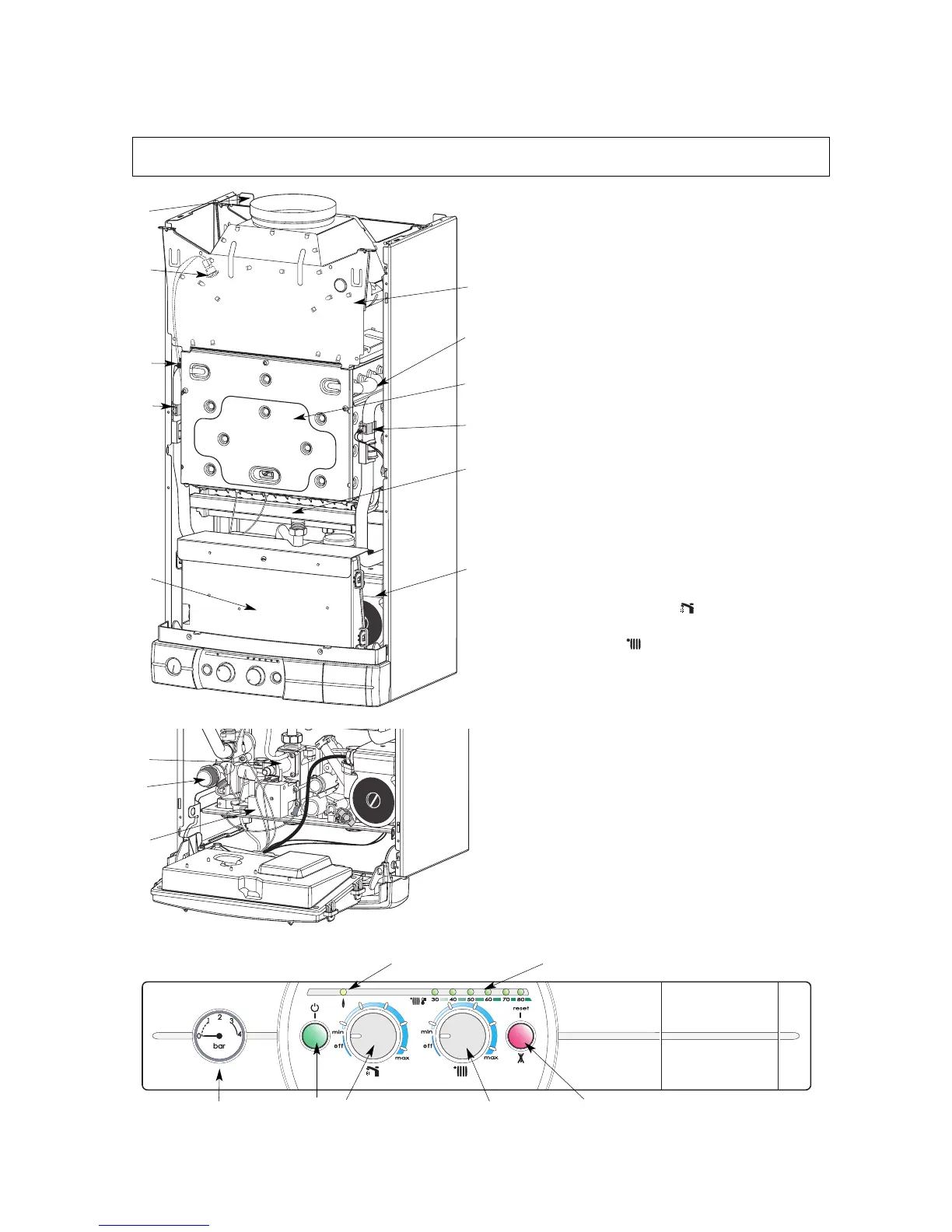
Fig.1
1
2
4
5
6
12
3
10
8
9
11
1.- sheet steel frame with expansion vessel
2.- overflow safety device
3.- draught diverter
4.- copper main heat exchanger
5.- combustion chamber
6.- multigas burner comprising:
• a removable injector manifold
• a ignition electrode
• a flame detection electrode
7.- gas valve assembly comprising:
• two safety solenoid valves
• a control solenoid valve
8.- circulating pump with automatic vent
9.- overheat sensor
10.- main heat exchanger inlet thermistor
11.- main heat exchanger outlet thermistor
12.- electronic control unit
15.- ignitor
16.- central heating pressure relief valve
19. - heating circuit pressure gauge
20. - ON/OFF push button and ON indicator light
21.- sanitary accumulation start button and tank
temperature setting button
22.- heating function ON and heating temperature
adjustment knob
23.- heating temperature and operating fault indicator
24.- orange burner operating indicator light
25.- reset push button and red locking indicator light.
1. Description
Fig.3
20
21
23
25
22
24
19
C
15
16
Fig.2
7
(system plus)
 Loading...