EasyManua.ls Logo

Challenger 9500M

Default Icon
20 pages
To Next Page IconTo Next Page
Loading...
INSTALLATION AND OWNER’S MANUAL
As of date of
manufacture, meets all
ANSI/UL 325 Safety
Requirements for
Vehicular Garage
Door Operators
110060
TABLE OF CONTENTS
Pre-Power On Installation Checklist ...............14
Section E: Operation & Adjustments.....................15
Important Safety Instructions .........................15
Turning on the Power ......................................15
Basic Operating Parameters ...........................15
Manual Door Operation..................................... 9
Adjustments .....................................................16
Opening Travel Adjustments...........................16
Open & Closing Force Adjustment .................16
Setting The Close Limit ...................................16
Obstruction Sensing Adjustment....................16
Testing The Obstruction Sensing ...................17
Positive Mechanical Lock Adjust ....................18
Alignment of Safe Finish Photoelectric ..........18
Photoelectric Obstruction Test .......................18
Wiring Diagram .......................................................19
Troubleshooting Guide ..........................................19
Warranty Information .............................................20
INSTALLER: Place this manual in the plastic envelope provided and
permanently attach to the wall near the pushbutton.
READ THIS MANUAL CAREFULLY BEFORE INSTALLATION OR USE
WARNING
Indicates a
MECHANICAL
hazard of INJURY
OR DEATH. Gives
instructions to avoid
the hazard.
CAUTION
READ THESE STATEMENTS CAREFULLY AND FOLLOW THE INSTRUCTIONS CLOSELY
The Warning and Caution boxes throughout this manual are there to protect you and your equipment.
Pay close attention to these boxes as you follow the manual.
WARNING CAUTION
Indicates an ELECTRICAL
hazard of DAMAGE to the
door, door operator, or
equipment. Gives
instructions to avoid the
hazard.
Indicates an
ELECTRICAL hazard
of INJURY OR
DEATH. Gives
instructions to avoid
the hazard.
Indicates a MECHANICAL
hazard of DAMAGE to the
door, door operator, or
equipment. Gives
instructions to avoid the
hazard.
Product Features ......................................................2
Tools Required..........................................................2
Component Identification ........................................3
A: Assembly Instructions ....................................3
Identify Your Door Type ...........................................4
B: Important Installation Instructions.....................5
C: Installing the Operator ........................................6
Mounting the Front Bracket...............................6
Mounting the Power Head .................................7
Door Bracket Installation...................................7
Door Arm Installation.........................................8
Connecting Electrical Power .............................9
The Convenience Lamp .....................................9
D: Control & Auxiliary Equipment..........................10
Standard Wall Button Installation ...................10
Programming the Radio Transmitter ..............11
Programming the Radio Receiver ...................13
Safe Finish™ Photosystem Installation..........13
SAVE THESE INSTRUCTIONS
BY
CHALLENGER 9000M SERIES
Residential Vehicular Garage Door Operator
MODEL NUMBERS 9300M, 9500M, and J9500M
Question and Answer IconNeed help?

Do you have a question about the Challenger 9500M and is the answer not in the manual?

Challenger 9500M Specifications

General IconGeneral
Horsepower1-1/4 HP
Voltage120V
Motor TypeDC
Remote Controls2
WarrantyLifetime

Summary

Product Features

Standard Features Overview

Details on standard features like radio controls, photosystem, and alternating action.

Optional Features Overview

Description of optional features such as the keyless entry system.

Tools Required for Installation

Component Identification

Assembly Instructions Overview

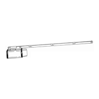
Overview of the assembly process, starting with rail and power head unit attachment.

Door Type Identification

Important Installation Safety Instructions

Installing the Operator - Front Bracket and Rail

Mounting the Front Bracket

Instructions for mounting the front bracket on sectional and one-piece doors.

Connecting Rail to Power Head Unit

Steps to connect the rail assembly to the power head unit and initial mounting.

Installing the Operator - Power Head Mounting

Mounting the Power Head to Ceiling

Guidance on securely mounting the power unit to ceiling joists for operational strength.

Installing the Door Bracket

Steps for mounting the door bracket to the garage door, including reinforcement needs.

Connecting Door Arm and Trolley

Connecting Door Arm to Trolley

Instructions for assembling and connecting the door arm to the trolley for sectional doors.

Connecting Door Arm to Door

Steps for attaching the door arm to the door bracket or strut mount.

One Piece Door Arm Assembly

Specific instructions for connecting the door arm for one-piece doors.

Electrical Connection and Manual Release

Manual Release Disconnect Operation

How to operate the manual release for door access during power failures.

Connecting Electrical Power

Guidelines for connecting the opener to the power source, including GFI and wiring.

Control and Auxiliary Equipment - Wall Button

Installing the Standard Wall Push Button

Steps for mounting the wall push button and connecting its wiring.

Control and Auxiliary Equipment - Radio System

Remote Control Radio System Setup

Instructions for programming the transmitter codes and using express coding.

Control and Auxiliary Equipment - Transmitter

Teaching the Operator the Transmitter Code

Process for teaching the opener to recognize transmitter signals and checking operation.

Safe Finish Photosystem Installation

Mounting and Connecting the Photosystem

Steps for mounting the photosystem brackets and connecting the wires.

Pre-Power On Installation Checklist

Operation and Adjustment Instructions - Safety and Basics

Important Safety Instructions for Operation

Critical safety warnings for operating the garage door opener.

Basic Operating Parameters

Explains how the opener responds to wall button and radio control inputs.

Operation and Adjustment - Travel Limits and Force

Adjustment #1: Opening Travel

Setting the open limit stops to ensure the door travels to the fully open position.

Adjustment #2: Opening and Closing Force

Adjusting the force settings for opening and closing to meet safety requirements.

Adjustment #3: Setting Door Close Limit

Establishing the correct trolley position for the fully closed door state.

Operation and Adjustment - Obstruction Sensing

Adjustment #4: Obstruction Sensing

Adjusting the door's sensitivity to reverse upon encountering an obstruction.

Important Test: Opener Obstruction Sensing

Procedure for testing the obstruction sensing feature monthly.

Operation and Adjustment - Lock and Photosystem

Adjustment #5: Positive Mechanical Lock Adjustment

Adjusting the automatic mechanical locking system for the closed position.

Adjustment #6: Alignment and Initial Test of Safe Finish Photosystem

Aligning and testing the Safe Finish Photosystem for proper beam detection.

Important Test: Photoelectric Obstruction Test

Testing the photoelectric sensor's ability to detect and react to obstructions.

Wiring Diagram and Troubleshooting

Wiring Diagram Overview

Diagram illustrating field wiring connections for the opener system.

Troubleshooting Guide

Diagnostic chart to identify and resolve common operational problems using LED indicators.

Manufacturers Limited Warranty

Related product manuals